


English 13
6. Connect the “pigtail” to the connector inside the
junction box.
7. Close the junction box cover.
8. Run five (5) wires (#14 AWG) in 1'' (25.4 mm) conduit
from the inline blower to the second conduit connector.
9. Connect the inline blower to the pigtail wires as per
Figure 14
. Connect the inline blower green (ground)
wire to the ground screw in the junction box.
Remote Control Installation
(optional)
NOTE: When using the Custom Insert with the optional
remote control, the unit loses the “AUTO” function and
the over-temperature heat sensor described in the Use
& Care Guide.
It is recommended that the Remote Control be wired to the
hood after the hood is installed.
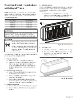
1. Access wiring
a) Remove filters, spacers and grease trays.
b) Remove the junction box cover (refer to
Figure 7
on page 10)
.
c) Remove three screws holding stainless steel panel
to the canopy.
d) Remove core partition (
Figure 16
).
2. Connecting the harness to the relay board.
a) Unplug harness from the remote control to the
relay board (
Figure 17
).
b) Plug in harness included in the remote kit
(
Figure 17
).
c) Run harness through core partition hole
(
Figure 18
).
Figure 14: Wiring the Hood with an Inline Blower
Figure 15: Remove stainless steel panel
SPEED 1
SPEED 2
SPEED 3
NEUTRAL
RD
BU
BN
WH
SP4
GROUND
N
SP1
SP2
SP3
Brown
Brown
Brown
Green/Yellow
Green/Yellow
Green/Yellow
White
White
White
Red
Red
Red
Blue
Blue
Blue
Orange
Orange
Orange
WH / BC / BL (16 AWG)
BK / N / NE (16 AWG)
120V, 60HZ, 20A
POWER SUPPLY
L1
N
T1
T2
S3
Figure 16: Remove core partition
Figure 17: Relay Board Hookup
Figure 18: Wire Routing through Partition


