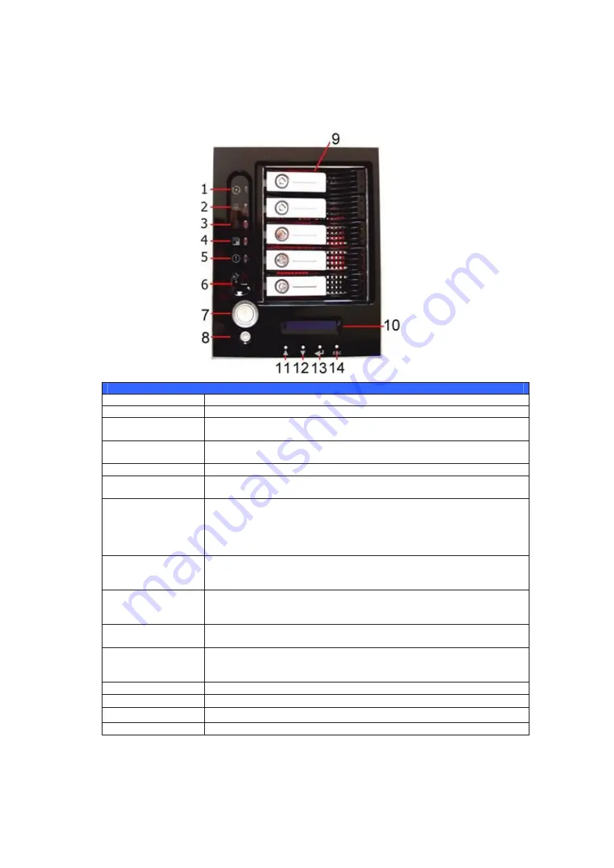
background image


10 

Front Panel 

The Thecus N5200PRO’s front panel has the device’s controls, indicators, and 
hard disk trays: 


Front Panel 

Item 

Description 

DOM LED 


Solid orange: system is being upgraded 

WAN LED 


Solid green: network link 


Blinking green: network activity 

LAN LED 


Solid green: network link  


Blinking green: network activity 

USB Copy LED 


Solid blue: files are being copied from a USB storage device 

Busy LED  


Blinking orange: system startup or system maintenance; data 
currently inaccessible 

USB Port 


USB 2.0 port for compatible USB devices, such as digital 
cameras, USB disks, USB printers, and USB wireless dongles* 

 
Note: For supported USB wireless dongles, please contact 
[email protected] 

Power Button 


Power on/off N5200PRO 


Solid blue: Device is powered on 


Blinking blue: eSATA hard disk is connected and active 

Reset Button 


Resets the N5200PRO 


Press for five seconds during boot process to reset IP address 
and admin password 

HDD Trays 


Five 3.5” SATA HDD trays 


Locks are provided for added security 

LCD Display 


Displays current system status and warning messages 


Displays hostname, WAN/LAN IP address, RAID status, and 
current time 

Up Button 


Push to scroll up when using the LCD display 

Down Button 


Push to scroll down when using the LCD display 

Enter Button 


Push to confirm information entered into the LCD display 

Escape Button ESC 


Push to leave the current LCD menu 


Summary of Contents for N5200B PRO

Page 1: ...Thecus N5200B PRO N5200BR PRO User s Manual...

Page 2: ...se provide us with your feedback Thecus Technology Corporation reserves the right to modify the contents of this manual without notice Product name Thecus N5200PRO Manual Version 1 2 Release Date May...

Page 3: ...elative humidity of 20 85 Using the N5200PRO under extreme environmental conditions could damage the unit Ensure that the N5200PRO is provided with the correct supply voltage AC 100V 240V 50 60 Hz 3A...

Page 4: ...are Installation 13 Overview 13 Before You Begin 13 Hard Disk Installation 13 Cable Connections 14 Checking System Status 15 System Status Normal 15 System Trouble 15 Chapter 3 First Time Setup 16 Ove...

Page 5: ...l List ACL 39 File System Check 40 Network Management 42 WAN Configuration 42 LAN Configuration 43 DHCP Configuration 43 WLAN Configuration 44 WAN LAN Exchange 45 Web Services Configuration 45 AFP App...

Page 6: ...Backup Utility 71 Windows XP Data Backup 72 Apple OS X Backup Utilities 72 Chapter 7 Tips and Tricks 73 USB and eSATA Storage Expansion 73 Adding a Spare Disk 73 Target USB 73 Remote Administration 74...

Page 7: ...RAID 5 82 RAID 6 82 RAID 10 82 JBOD 82 Stripe Size 82 Disk Usage 83 Appendix D Active Directory Basics 84 Overview 84 What is Active Directory 84 ADS Benefits 84 Appendix E UPS Compatibility List 85...

Page 8: ...allows you to store and share files over an IP network With a Network Attached Storage NAS device you can centralize your files and share them easily over your network With the easy to use web based...

Page 9: ...mate flexibility to users To set up an iSCSI volume refer to Chapter 4 System Management Storage Management Space Allocation Allocating Space for iSCSI Volume Superior Power Management N5200PRO suppor...

Page 10: ...d USB wireless dongles Note For supported USB wireless dongles please contact support thecus com Power Button Power on off N5200PRO Solid blue Device is powered on Blinking blue eSATA hard disk is con...

Page 11: ...PRO s rear panel features ports and connectors N5200B PRO Back Panel Item Description eSATA Port eSATA port for high speed storage expansion USB Port USB 2 0 port for compatible USB devices such as d...

Page 12: ...t target For connecting the N5200 to your PC as a mass storage device 4 port Gigabit Switch This 4 port switch can be used for connection sharing LAN Port LAN port that can be used for connection shar...

Page 13: ...Be careful not to use magnetized screwdrivers around the N5200PRO s electronic components Hard Disk Installation The N5200PRO supports five standard 3 5 Serial ATA SATA hard disks To install a hard di...

Page 14: ...work to the WAN port on the back panel of the N5200PRO 2 Connect the provided power cord into the universal power socket on the back panel Plug the other end of the cord into a surge protector socket...

Page 15: ...both are connected 2 The Power LED on the Front Panel glows blue 3 The HDD Power LED on each HDD tray glows blue assuming all disks are installed 4 The default IP address of the WAN port is 192 168 1...

Page 16: ...Wizard perform the following steps 1 Insert the installation CD into your CD ROM drive the host PC must be connected to the network 2 The Setup Wizard should launch automatically If not please browse...

Page 17: ...P address is recommended You may also use a static IP address and enter the DNS Server address manually 7 Change the default administrator password 8 Finished Access the N5200PRO Web Administrator Int...

Page 18: ...parameter setting ESC Escape Escape and return to the previous menu There are two modes of operation for the LCD Display Mode and Management Mode Display Mode During normal operation the LCD will be i...

Page 19: ...k of your WAN ports LAN Setting IP address and netmask of your LAN ports Link Agg Setting Select Load Balance or Failover N5200B PRO only Change Admin Passwd Change administrator s password for LCD op...

Page 20: ...n configuring Active Directory see Chapter 4 System Management User and Group Management ADS NT Configuration For information about the benefits of Active Directory see Appendix D Active Directory Bas...

Reviews: