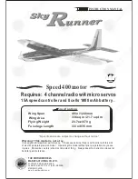
The World Models Manufacturing Sky Runner Instruction Manual Download Page 8

P.7 

 C a nopy

Radio Equipment

Rudder Servo

Rudder Pushrod

Straper

Elevator Pushrod Elevator Servo

Battery Tie

Install and arrange the servo as shown in the diagram.

Receiver


Sponge

15A Speed Controller

Speed 400 Motor

Double-Sided Tape

Completed

Battery

Fuel Tube

Ø

4x4mm

8

10

Nylon


Bolt


M2

.

5x16mm

2

2


Nylon


Washer


d2

.

6xD9mm

Peel off shaded portion covering film.

Nylon


Bolt


M2

.

5x16mm


Nylon


Washer


d2

.

6xD9mm

Wing Protection
0.8 x 20 x 42mm

2.5mm

M2

.

5x16mm

d2

.

6xD9mm

Main Wing

9

Bottom View

Summary of Contents for Sky Runner

Page 1: ...this model without prior preparation may cause injuries Remember safety is the most important thing Always keep this instruction manual at hand for quick reference THE WORLD MODELS MANUFACTURING CO LTD FACTORY PRE FABRICATED ALMOST READY TO FLY ARF SERIES MADE IN CHINA www theworldmodels com Specifications are subject to change without notice Specifications Speed 400 motor Requires 4 channel radio...

Page 2: ...ea of what to do Symbols used throughout this instruction manual comprise of the following Ensure smooth non binding movement while assembling Apply instant glue C A glue super glue Assemble left and right sides the same way Apply epoxy glue 1 2 3 Check all parts If you find any defective or missing parts contact your local dealer Please DRY FIT and check for defects for all parts that will requir...

Page 3: ... D ECALS 1 set 1 MAIN WING 1 pc WING JOINER 4 5x109mm 1 pc 2 SCREW PM2x12mm 4 pcs STRAPER 2 pcs FUEL TUBE d2xD4x4mm 4 pcs CLEVIS 2 pcs HORN 2 sets PUSHROD 1 4x72mm w Threads For Aileron Servo 2 pcs 3 STABILIZER ELEVATOR 1 set FUSELAGE 1 pc BAMBOO Ø3 x10 mm 1 pc 4 VERTICAL FIN RUDDER 1 set 5 SCREW PM2x8mm 2 pcs CLEVIS 1 pc FUEL TUBE d2xD4x4mm 1 pc HORN 1 set PUSHROD 1 4x500mm w Threads For Elevator...

Page 4: ...i horn are pre drilled Please look for pin hole marks at under side of control surfaces 2mm Bottom View PM2 x12mm Pushrod Clevis Horn Fuel Tube d2xD4X4mm stra per 1mm Ø1 4x72mm 2mm Completed Apply instant type CA glue to both sides of each hinge Wing Joiner Ø4 5 x 109mm Aileron Servo Lead ...

Page 5: ...d Portion covering film Peel off shaded Portion covering film Stabilizer Elevator 3 A A A A Stabilizer Main Wing B B Temporary install the main wing adjust leveling of the stabilizer to make it as parallel to the main wing as possible Apply instant type CA glue to both sides of each hinge Completed BAMBOO Ø3x10mm ...

Page 6: ... are pre drilled Please look for pin hole marks at side of control surfaces 7 Rudder Pushrod 6 6mm 6mm m 110 m Bottom View PM2 x 10mm Clevis Horn 2mm Pushr od 1 4 x 445m m Fuel Tube 86mm 10 m m 10 m m d2xD4x4mm Pushr od 1 4 x 445m m Pushr od 1 4 x 500m m 5 Ø1mm pilot holes for World Models tri horn are pre drilled Please look for pin hole marks at under side of control surfaces Ø1mm pilot holes fo...

Page 7: ... M2 6x7mm Screw 1 3mm Set Screw PM2 x 12mm Screw 4 2 PA2 6 x 10mm Screw 1 m m TO ALLOW FOR BACKLASH OF MATCHING GEAR PUT A PIECE OF THIN PAPER BETWEEN THE GEARS AND THEN TIGHTEN THE M2 6x7mm SCREWS REMOVE THE PAPER BEFORE FLYING PM2 x 12mm 6 PM2 x 12mm M2 Nut 2 d2 x D5mm Washer 2 d2 x D5mm PM2 x 12mm M2 Nut M2 6 x 7mm ...

Page 8: ...shown in the diagram Receiver Sponge 15A Speed Controller Speed 400 Motor Double Sided Tape Completed Battery Fuel Tube Ø4x4mm 8 10 Nylon Bolt M2 5x16mm 2 2 Nylon Washer d2 6xD9mm Peel off shaded portion covering film Nylon Bolt M2 5x16mm Nylon Washer d2 6xD9mm Wing Protection 0 8 x 20 x 42mm 2 5mm M2 5x16mm d2 6xD9mm Main Wing 9 Bottom View ...

Page 9: ...A A P 8 Wing Setting 11 Adj ust the wing and fuse lage con figur ation as sho wn in the diagr ams A A B B C C B B C C ...

Page 10: ...s Please begin with lower temperature setting and gradually raise the temperature until the wrinkles are gone Too hot an iron may damage the covering Check and re tighten up all factory assembled screws use thread locker if applicable Warning P 9 C G 13 The ideal C G position is 52mm 2 0 in behind the leading edge measured at where the wing meets the fuselage In order to obtain the C G Specified a...

Page 11: ... parts when applicable Please fill in the following and send to 1 Name 2 Address 3 Phone e mail 4 Model Wing QC Fuselage QC QC numbers are stamped on wing and fuselage 5 Date of Purchase 6 Store Name Please call AirBorne Models at 925 371 0922 for any assistance in filling this form Thank you very much for purchasing our product Air Borne Models 2403 Research Drive Livermore CA 94550 U S A P 10 ...

Page 12: ...Warbirds Scale Sports Trainer Covering Lightex Toughlon Accessories Pattern Funfly Electric Glider Boat http www theworldmodels com E2400606 ...

Reviews: