background image

Apply thread locker

P. 3 -14

Do not overlook this symbol!

Cut off shaded portion.

Peel off shaded portion
covering film.

Pay close attention here!

Pierce the shaded portion
covering film.

Must be purchased separately!

Drill holes with the specified
diameter (here:  3mm).

3mm

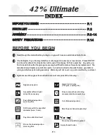
I N D E X

BEFORE YOU BEGIN

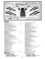
PARTS LIST

ASSEMBLY

SAFETY   PRECAUTIONS

P. 1

P. 2

P. 14

BEFORE  YOU  BEGIN

Read through the manual before you begin

,

 so you will  have an overall idea of what to do.

Symbols used throughout this instruction manual  comprise of the following : -

Ensure smooth non-binding
movement while assembling.

Apply instant glue
(C.A.glue,  super glue.)

Assemble left and right
sides the same way.

Apply epoxy glue. 

1

2

3

P.1

Check all parts. If  you find any defective or missing parts contact your  local dealer.  Please DRY FIT


and check for defects for all parts that  will  require CA or Epoxy  for final  assembly.   Any parts  you


find to be defective after the gluing process may be difficult to remove for warranty replacement.  The


manufacturer will replace any defective parts.  but will not extend to the parts that are good before 


gluing to defective parts during assembly. Warranty


will


not


cover


any


parts


modified


by


customer

.


Summary of Contents for 42% ULTIMATE

Page 1: ...ation may cause injuries Remember safety is the most important thing Always keep this instruction manual at hand for quick reference Requires 150 cc gasoline engine 6 channel radio w 17 servos Specifications are subject to change without notice Specifications INSTRUCTION MANUAL EA D R Y T T S O O F M L L Y A 42 42 98 in 2490mm 3300 sq in 213 sq dm 38 40 lbs 17250 18160 g 104 in 2640mm FACTORY PRE ...

Page 2: ...ual comprise of the following Ensure smooth non binding movement while assembling Apply instant glue C A glue super glue Assemble left and right sides the same way Apply epoxy glue 1 2 3 P 1 Check all parts If you find any defective or missing parts contact your local dealer Please DRY FIT and check for defects for all parts that will require CA or Epoxy for final assembly Any parts you find to be...

Page 3: ...43mm F63C 1 pc 8 CENTER WING CABANE 1 set ALUMIMUM PLATE 2 pcs SCREW PM3x16mm 6 pcs WASHER d3xD7mm 12 pcs M3 NYLON INSERT LOCK NUT 6 pcs BALSA 9x9x411 4mm F63A For Fuselage 2 pcs BALSA 9x9x402 3mm F63B For Fuselage 2 pcs 9 MAIN LANDING GEAR 1 set SOCKET HEAD SCREW M6x20mm 4 pcs AXLE SHAFT Ø5x47mm 2 pcs SCREW PA3x12mm 4 pcs SCREW PM3x16mm 4 pcs WASHER d3xD7mm 4 pcs COLLAR Ø5 1mm w set screw 4 sets ...

Page 4: ... Aileron Servo 2 Bottom View Upper Wing Bottom View Outer wing cabane mounts Heavy Duty Clevis M2 Nut PM2x8mm Wood 6X10X21mm Pushrod PM4x50mm M4 Nylon Insert Lock Nut PM2x8mm M2 Nut Heavy Duty Clevis PA1 7x8mm 3 7mm Drill and tap the swivel clevis horn locations for M4 machine screw M4 Tap Heavy Duty Horn Bracket PM2x8mm M2 Nut PL4120350 M4 Nylon Insert Lock Nut PM4x50mm Screw 4 4 ...

Page 5: ...w PWA3x14mm Bottom View Wire Ø3x192mm Bottom View M3x6mm set screw M3x6mm set screw M3x6mm set screw PWA3x14mm 2mm M4 Nylon Insert Lock Nut PM4x50mm Screw 4 4 M4 Nylon Insert Lock Nut PM4x65mm Screw 4 4 PWA3x14mm Screw Pushrod PM4x65mm M4 Nylon Insert Lock Nut PM2x8mm M2 Nut Heavy Duty Clevis PA1 7x8mm 3 7mm Drill and tap the swivel clevis horn locations for M4 machine screw M4 Tap Heavy Duty Horn...

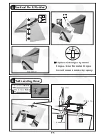
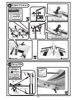
Page 6: ...pleted B B B B Replace CA hinges by metal hinges Glue the metal hinges to vertical and rudder by epoxy Tail Landing Gear 6 P 5 Bottom View PWA2 5 x 12mm PA3 5 x16mm 1mm COPPER PLATE 1 5mm PA3 5x16mm Screw 4 4 PWA2 5x12mm Screw ...

Page 7: ...se epoxy to glue all parts together Please note right thrust angle of firewall F10 M3 Nylon Insert Lock Nut PM3x16mm M3 Nylon Insert Lock Nut PM3x16mm Screw 16 d3xD7mm Washer d3xD7mm Washer 8 8 0 F9 F9A F9B F10 F10 F8A F63C F9J 3 F9D F8L F9H F9F F9C F9E F8R F9 F9E F8B F9J ...

Page 8: ...ylon Inert Lock Nut d3xD7mm Washer d3xD7mm Washer d3xD7mm Washer d3xD7mm Washer M3 Nylon Inert Lock Nut F36A F36B M3 Nylon Insert Lock Nut PM3x16mm Screw 12 d3xD7mm Washer 6 PM3x16mm PM3x16mm Ø5x54 5mm Axle Shaft 2 M8 Nylon Inert Lock Nut 2 Ø5x54 5mm M8 Nylon Inert Lock Nut 4 d3xD7mm Washer 4 PA3x12mm Screw PM3x16mm d3xD7mm Washer 5 1mm Collar 4 5 1mm Collar Wheel 128mm Ø 5 1mm Collar 6 M6x20mm So...

Page 9: ...mm Set Screw 4 d3 6mm Collar PM 3x30mm Screw 3 3 M3 NYLON INSERT LOCK NUT Bottom View M4 Nylon Insert Lock Nut 2 2 PM2x10mm Screw M4 M4 Nylon Insert Lock Nut PA1 7x8mm M4 Tap 3 7mm Drill and tap the swivel clevis horn locations for M4 machine screw PM2x8mm 1mm M2 Nut 1mm Heavy Duty Clevis PM2x8mm PM2x8mm M2 Nut M2 Nut Heavy Duty Clevis Bottom View PM2x10mm M2 Nut M2 5 PM2x10mm PM2 x 0mm 5 3 Comple...

Page 10: ...ment Install and arrange the receiver and battery as shown in the diagram Sponge Front d3xD7mm Washer Fuel Tank 1500cc Sponge to cushion fuel tank Plywood 3x130x239mm F15A Tongue Cable Tie 2 d3xD7mm Washer 2 M3x12mm M6x50mm SOCKET HEAD SCREW 4 M6 Blind Nut 4 d6xD15mm Washer 4 M3x12mm SOCKET HEAD SCREW ...

Page 11: ...firm the alignment of the hole by putting a 2 5mm diameter rod through the pre drilled wing hole before applying the screw The hole on the wing tube is pre thread do not over tighten the PM3 screw the set up is for future removal of the wing Wing Tube Ø22x865 5mm 255mm Main Wing Lower 1 Step 165mm Step 2 Install the right wing to the fuselage by inserting the wing tube now attached to the right wi...

Page 12: ...are resting against the center wing cabane tightly Locate the pre drilled 2mm hole at top of left wing and drill along with 2 5mm drill bit until it passes through the w i n g t u b e A p p l y t h e PA 3 x 2 2 m m s e l f t a p p i n g s c r e w 164mm 380mm d3 x D7mm Washer PM3x22mm Screw 1 2 PA3x22mm Screw 1 PM3x22mm d3 x D7mm Washer PAx22mm d3 x D7mm Washer Top View Step 1 Insert the aluminum w...

Page 13: ...ng incidence angle template still in place position the side cabanes mark and drill the side cabane mounts and fasten with PM3x18mm screw and nut 8 P 12 18 Canopy First insert the grommet to the canopy then apply screw PM3x25mm d3xD7mm Washer PLYWOOD 3x536 6x597 4mm WING INCIDENCE ANGLE TEMPLATE d3 x D7mm Washer 4 PWA2 3x8mm Screw 4 4 d1 5xD6 5mmSilicon Grommet PM3x25mm Screw 4 PWA2 3x8mm Pilot d1...

Page 14: ...are resting against the center wing cabane tightly Locate the pre drilled 2mm hole at top of left wing and drill along with 2 5mm drill bit until it passes through the w i n g t u b e A p p l y t h e PA 3 x 2 2 m m s e l f t a p p i n g s c r e w 164mm 380mm d3 x D7mm Washer PM3x22mm Screw 1 2 PA3x22mm Screw 1 PM3x22mm d3 x D7mm Washer PAx22mm d3 x D7mm Washer Top View Step 1 Insert the aluminum w...

Page 15: ...ng incidence angle template still in place position the side cabanes mark and drill the side cabane mounts and fasten with PM3x18mm screw and nut 8 P 12 18 Canopy First insert the grommet to the canopy then apply screw PM3x25mm d3xD7mm Washer PLYWOOD 3x536 6x597 4mm WING INCIDENCE ANGLE TEMPLATE d3 x D7mm Washer 4 PWA2 3x8mm Screw 4 4 d1 5xD6 5mmSilicon Grommet PM3x25mm Screw 4 PWA2 3x8mm Pilot d1...

Page 16: ...G G E E 3 19 Cowling Spinner First insert the grommet to the cowling then apply screw A A d2 5xD8 5mm Silicon Grommet 1 5mm Spinner Ø150mm d2 5 x D8 5 mm Silicon Grommet 6 6 PWA3x12mm Screw PWA3x12mm Adjust the wing and fuselage configuration as shown in the diagrams ...

Page 17: ...result of weather changes you can use hot iron to remove the wrinkles Please begin with lower temperature setting and gradually raise the temperature until the wrinkles are gone Too hot an iron may damage the covering Check and re tighten up all factory assembled screws use thread locker if applicable 150cc 200cc Adjust the control throws as shown in the diagram These throws are good for general f...

Page 18: ...anufacturing Co LTD www theworldmodels com Wa r b i r d s S c a l e S p o r t s T r a i n e r Du c t e dF a n Pa t t e r n F u n f l y E l e c t r i c Gl i d e r Bo a t A c c e s s o r i e s Co v e r i n g L i g h t e x T o u g h l o n ...

Reviews: