


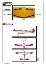

Cowling
16
d1.5 x D6.5 mm
Silicon Grommet
PWA2
.
6 x 12mm
Screw
4
4
2mm
Spinner
Ø62mm
Canopy
d1.5 x D6.5 mm
Silicon Grommet
PWA2
.
3 x 12mm
Screw
4
4
d1.5 x D6.5 mm
Silicon Grommet
2mm
PWA2
.
3 x 12mm
First
insert
the
grommet
to
the
canopy
then
apply
screw
.
17
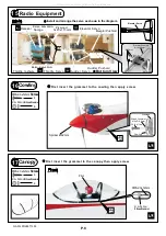
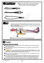
Radio
Equipment
15
Install and arrange the servo as shown in the diagram.
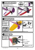
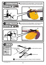
Elevator
Pushrod
Front
Fuel
Tube
Ø
6x5mm
Sponge
Straper
Rudder
Pushord
Elevator
Servo
KM 2x8mm
M2 Nut
Elevator Pushrod
Ø1.8x90mm
Bottom View
Plywood
3x49x113mm
P.8
First
insert
the
grommet
to
the
cowling
then
apply
screw
.
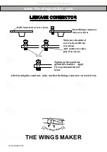
Receiver
Rudder
Servo
Elevator Servo
Throttle
Servo
PWA2.6x12mm
Silicon Grommet
d1
.
5xD6
.
5mm
Cowling
Fuselage
Front
Pilot
Throttle
Pushwire
Balsa
6x6x46mm
Balsa
6x6x46mm
GA014PO28971303
All manuals and user guides at all-guides.com


