


P.10
30mm
9mm
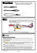
Adjust
the
control
throws
as
shown
in
the
diagram
These
throws
are
good
for
general
flying
.
Yon
can
adjust
according
to
your
personal
preference
.
.
First time flyer should never fly by himself / herself. Assistance from experienced flyer is
absolutely necessary.
Pre - flight adjustment must be done before flying, it is very dangerous to fly a badly
adjusted aircraft.
pre -
Make sure the air field is spacious, never fly the plane too close to people and never get
too close to a running propeller.
If you find wrinkles on the covering as a result of weather changes, you can use hot iron
to remove the wrinkles. Please begin with lower temperature setting and gradually raise
the temperature until the wrinkles are gone. Too hot an iron may damage the covering.
Check and re-tighten up all factory assembled screws, use thread locker if applicable.
30mm
9mm
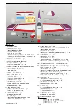
is specially designed to be powered by
2C
0.40
-
0.46
/
4c
0.70
stroke
glow engine, using a more powerful engine does not mean better performance. In fact,
over powered
engine may cause severe damage and injuries.
18mm
18mm
Elevator
Rudder
Ailerons
Important Safety Precautions
3.9in
100mm
100mm
3.9in
http://www.thewingsmaker.com/instructionManuals.php
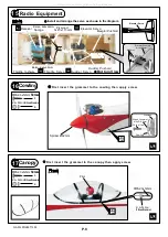
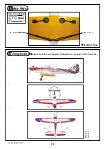
The ideal C.G. position is 100mm (3.9in.) behind the leading edge measured at where the wing meets the
fuselage. In order to obtain the C.G. specified, add weight to the fuselage or move the battery position.
Check the C.G. before flying.
If you are converting this model to electric, please move the C.G. forward 10% of current C.G. distance from
leading edge to compensate for weight of fuel.
Measure C.G. with the wheels in retracted position.
GA014PO28971303
All manuals and user guides at all-guides.com
all-guides.com


