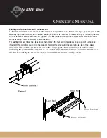
Maintenance of Top Rod Assembly
Annually apply a small amount of commercial grease to the top of the square bolt at the top of the door. In unusually
dirty situations a small amount of spray lubricant can be applied to the center gear mechanism by removing the edge
plate on the edge of the door.
To replace the rod mechanism it will be necessary to take the door down if it is less than 8' tall. For taller doors it will
most likely be necessary to take the door out of the frame.
To remove the top rod assembly, first remove the cover plate from the locking edge of the door. Then remove the lever
trim. Remove both end caps and push bar from the device. Remove the two sem screws from the link arm. Holding
the rod assembly through the access hole in the door edge, remove the two screws from the edge of the panic bar
cutout and pull the top rod assembly out through the access hole.
Owner's Manual
#10-32 x 1/2" Sems Screw
(6) req'd ( S277-10R08-603 )
#10-32 x 3/8" Sems Screw
(2) req'd ( S277-10R06N-603 )
#10-32 x 1 7/16" Flat Head
(4) req'd ( S258-10R23-119 )
#10-32 x 1/2" Flat Head
(2) req'd ( S266-10R06-603 )
#10-32 x 1/4" Sems Screw
(2) req'd ( S277-10R04N-603 )
1
2
3
4
5
Screw List
Latch End
Hinge End
Screw List
Item 1
Screw List
Item 2
Screw List
Item 2
Screw List
Item 5
Connecting
Link
Center
Block
Screw List
Item 4
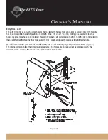
To replace, first remove the top latch assembly from the top edge of the door by removing the four screws. Adjust
the new rod length as the old rod, making sure the top square bolt is threaded about half way giving you optimum
adjustment. With the rod at the correct length, screw the cap head screw all the way through the rod. Push the rod
assembly up through the access hole making sure the trim adapter is facing the pull side of the door. Pull the link
arm through to the exit device cutout. Push the gear assembly up to the edge of the push bar cutout and screw into
place. The link arm goes over the slide arm of the exit device, and then replace the sems screws.
Replace the top latch over the square bolt making sure pins in the square bolt are oriented to the slot in the top
assembly as outlined in the top actuator section.


