TFT AXD1ST-NX-F Instructions For Installation, Operation And Maintenance Download Page 21

©Copyright Task Force Tips LLC 2014-2021

21

LIA-208 May 19, 2021 Rev05

8.4 CRANKSHAFT OVERRIDE AND REPLACEMENT

The  crankshaft  includes  an  intentional  shear  joint  to  protect  the  gear  train  from  overload,  costly  repairs,  and  loss  of  service.  The

magnitude of torque required to shear the crankshaft is several times greater than the torque typically needed to operate the valve at

maximum operating pressure. If the crankshaft breaks during use, this is an indication that either there is something obstructing the half

ball internally. or the crank shaft has been abused (e.g. used as a step for climbing).

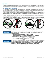
8.4.1 EMERGENCY CRANKSHAFT OVERRIDE

In an emergency, the opposite side of the crankshaft can be turned using a 1/2” wrench or hex socket. This allows the valve to be open

or closed until the crankshaft is replaced. To prevent loss of the 1/8” square key on the crankshaft, do not allow the crankshaft to slide

out of gearbox until a replacement crankshaft is on hand. It is important not to rely on the emergency override as a long-term method of

operation.

8.4.2 DIAGNOSING CRANKSHAFT FAILURE

To determine the cause of a crankshaft to failure, complete the following steps:

1. Close upstream water supply. If possible, relieve pressure leading up to valve.

2. Locate 1/2” hex where crankshaft protrudes from opposite side of gearbox.

3. Gently turn crank shaft away from travel stop using a ½” hex wrench. Do not attempt to shock crankshaft free and do not exceed

50 ft-lb (68 Nm) of torque.

4.

If crankshaft will not rotate

, half ball is likely obstructed. Only after relieving pressure on flanged joint, unbolt valve. Clear any

obstructions and evaluate whether repair is needed before returning to service.

5.

If crankshaft is able to rotate

, cycle the valve several times from open to closed to determine whether the crankshaft binds at

any place between the travel stops. If crankshaft binds, consult Task Force Tips Service Department to determine the appropriate

repairs.

6.

If crankshaft rotates freely after clearing any obstructions

, a replacement crank shaft may be ordered from Task Force Tips

and replaced as described below.

8.4.3 CRANKSHAFT REPLACEMENT

A broken crankshaft can be replaced at any time by completing the following steps, regardless of whether or not the upstream water

supply  is  pressurized.  Referring  to  item  numbers  shown  in  the  exploded  view  available  at TFT.com/serial-number,  follow  the  steps

below:

1. Remove external retaining ring (item 118) adjacent to ½” hex on crankshaft. Do not over-expand the retaining ring.

2. Using a punch or Phillips head screwdriver at least 6” in length, gently push on dimple in ½” hex end of crankshaft (item 131).

Continue to push crankshaft through until it protrudes from opposite side of gearbox.

3. Grab broken end of crankshaft and pull out of gearbox. As crankshaft is withdrawn, grasp small key (item 119) on shaft so it does

not get lost.

B. If 1/8” square x 1” long key is not visible in shaft, it has likely fallen into gearbox bore and must be removed before installing

new crankshaft. If square key is visible in gearbox bore, slide it out of bore. Needle-nose pliers may be helpful depending on

position of key in bore.

4. Verify polymer bushings (item 117 and 120) are still seated in bores on each side of gearbox. If not, locate and reinstall bushings.

5. Look through gearbox bore and note approximate orientation of square keyway in worm (item 115). Verify round notch in thrust

washer (item 116) is aligned with square keyway in worm.

6. Prepare new crankshaft by applying small dab of grease to keyway and seating 1/8” square x 1” long key into keyway. Grease will

keep key in place during assembly.

7. Slide shaft into gearbox with key orientation the same as keyway in worm. 

8. Rotate shaft slightly in alternating directions until key finds keyway, then push shaft in until it stops. Retaining ring groove and ½”

hex should be protruding through opposite side of gearbox. 

A. If hex is not visible, it may be necessary to slide polymer bushing back into gearbox bore.

9. Install retaining ring (item 118) onto shaft. Do not over-expand the retaining ring.
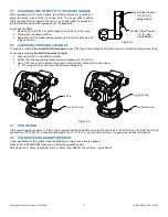
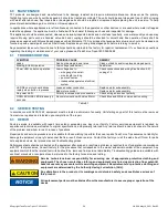
Figure 8.4.3

115

116

117

118

120

119

131

116

Summary of Contents for AXD1ST-NX-F

Page 1: ...ith the operation servicing and safety procedures associated with this product This manual should be kept available to all operating and maintenance personnel LEFT DRIVE RIGHT DRIVE AXD1ST NX T Jumbo...

Page 2: ...rns or other severe injury Fire and Emergency Manufacturers and Service Association Inc PO Box 147 Lynn eld MA 01940 www FEMSA org 2020 FEMSA All Rights Reserved PERSONAL RESPONSIBILITY CODE DANGER SU...

Page 3: ...FSET OF THE CRANK HANDLE 5 6 CHANGING COUPLING LOCK OUT 5 7 PEG OPTION 5 8 STORZ SUCTION GASKET REQUEST 6 0 USE 6 1 ELBOW 6 2 MANUAL VALVE OPERATION 6 3 RC VALVE OPERATION 6 4 AIR VENT AND WATER DRAIN...

Page 4: ...TION indicates a potentially hazardous situation which if not avoided could result in minor or moderate injury NOTICE NOTICE is used to address practices not related to physical injury DANGER An inade...

Page 5: ...o 135 F 32 to 57 C Materials Used Aluminum 6000 series hard anodized MIL8625 class 3 type 2 stainless steel 300 series For temperatures below 32 0 C valves must be drained after use to avoid damage Vo...

Page 6: ...ake Elbow Swivel Side B Coupling Valve Position Indicator Hand Crank Outlet Side A Coupling AZD1ST NX T Left Drive Jumbo Low Profile Ball Intake Valve Top Crank with Pressure Relief Valve Manual Overr...

Page 7: ...ith salt water is permissible provided the equipment is thoroughly cleaned with fresh water after each use The service life of the equipment may be shortened due to the effects of corrosion and is not...

Page 8: ...sition 6 9 174mm 6 8 172mm 8 4 213mm 6 9 174mm 6 8 172mm 8 4 213mm R3 4 R87 SWING R3 4 R87 SWING 11 3 286mm 8 7 221mm 7 2 183mm 5 6 142mm 5 6 142mm 12 2 309mm 7 2 183mm 9 4 240mm Top View Angled Posit...

Page 9: ...Position 12 3 312mm 5 6 142mm 4 8 122mm 8 7 221mm 8 4 213mm 6 8 172mm R3 4 R87 SWING 7 0 178mm 5 6 142mm 4 8 122mm 9 4 240mm 8 4 213mm 6 8 172mm 7 0 178mm R3 4 R87 SWING Front View Down Position Fron...

Page 10: ...122mm 8 7 221mm R3 4 R87 SWING 6 9 174mm Front View Down Position 8 4 213mm 6 8 172mm R3 4 R87 SWING Front View Angled Position 6 9 174mm 4 8 122mm 9 4 240mm 12 3 312mm 5 6 142mm Side View Down Positi...

Page 11: ...View Down Position 6 8 172mm 8 8 223mm 6 8 172mm 8 8 223mm 4 8 122mm 9 4 240mm 10 5 267mm 5 6 142mm 10 5 267mm 11 3 286mm 5 6 142mm 4 8 122mm 8 7 221mm Side View Angled Position Side View Down Positio...

Page 12: ...led together can cause galvanic corrosion that can result in the inability to uncouple the connection or complete loss of engagement over time Failure could cause injury Per NFPA 1962 if dissimilar me...

Page 13: ...Gel is non hazardous and should be wiped from conductors with a rag NOTICE To avoid excessive voltage drop at the valve motor do not lengthen factory supplied receptacle cable Power cable selection is...

Page 14: ...stop by current limit method A If motor continues to operate see proper voltage test above 4 Position indicator lights will now track valve movement 5 4 BIV RC MANUAL OVERRIDE The Ball Intake Valve R...

Page 15: ...ime swivel to rigid 1 Align the pull pin in the elbow to vertical 2 Rotate the coupling until the lockout screw is aligned with the pull pin 3 Use a 7 32 hex driver to tighten the lockout screw into t...

Page 16: ...will reach the positive stops when the handle is either parallel to the outlet OPEN position or perpendicular to the outlet CLOSED position Valves with hand cranks include a valve position indicator...

Page 17: ...s equipped with an air vent drain o the front of the unit which will allow the air to escape from the valve when the hose is charged The air vent drain is opened by turning the knob counter clockwise...

Page 18: ...mits The pressure relief valve meets the requirements of NFPA 1901 6 6 PRESSURE LOSS Figure 6 6 6 7 SUCTION SCREEN This device may be equipped with a suction screen to catch debris larger than 3 8 dia...

Page 19: ...less reasonable depreciation in complete discharge of its obligations under this limited warranty If TFT makes this election claimant shall return the equipment to TFT free and clear of any liens and...

Page 20: ...as to the nature of the problem and whom to reach in case of questions Repair parts and service procedures are available for those wishing to perform their own repairs Task Force Tips assumes no liab...

Page 21: ...6 If crankshaft rotates freely after clearing any obstructions a replacement crank shaft may be ordered from Task Force Tips and replaced as described below 8 4 3 CRANKSHAFT REPLACEMENT A broken crank...

Page 22: ...ce 11 There are no missing worn out or broken lugs on couplings 12 Hose is securely attached BEFORE BEING PLACED BACK IN SERVICE equipment must be inspected to this list 1 All valves open and close sm...

Page 23: ...Copyright Task Force Tips LLC 2014 2021 23 LIA 208 May 19 2021 Rev05 This page intentionally left blank...

Page 24: ...ATES 11 1 DISPLAY ENCLOSURE Figure 11 1 11 2 QUICK CONNECT PLUG Figure 11 2 HOLE LOCATIONS FOR BIV RC POSITION DISPLAY 7 32 5 5mm DIA 4 PLACES OR TAP FOR 10 32 UNC THREAD 3 1 2 89mm 3 1 2 89mm MOUNT E...

Reviews: