


©Copyright Task Force Tips LLC 2014-2021
12
LIA-208 May 19, 2021 Rev05
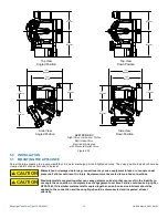
Figure 4.0F
5.0 INSTALLATION
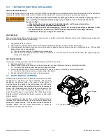
5.1 MOUNTING THE APPLIANCE
Screw the large coupling to a pump manifold or fire water discharge port and tighten securely. The valve position indicator should be
clearly visible, but does not need to be level.
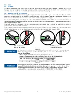
CAUTION
Mismatched or damaged waterway connections may cause equipment to leak or uncouple under
pressure. Failure could result in injury. Equipment must be mated to matched connections.
CAUTION
Dissimilar metals coupled together can cause galvanic corrosion that can result in the inability to
uncouple the connection, or complete loss of engagement over time. Failure could cause injury. Per
NFPA 1962, if dissimilar metals are left coupled together, an anti-corrosive lubricant should be
applied to the connection and the coupling should be disconnected and inspected at least
quarterly.
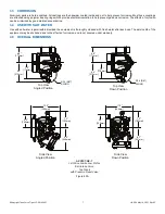
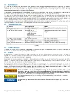
8.8"
[223mm]
6.8"
[172mm]
8.8"
[223mm]
6.8"
[172mm]
10.5"
[267mm]
12.2"
[309mm]
9.4"
[240mm]
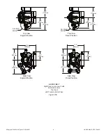
4.8"
[122mm]
5.6"
[142mm]
4.8"
[122mm]
8.7"
[221mm]
11.3"
[286mm]
10.5"
[267mm]
5.6"
[142mm]
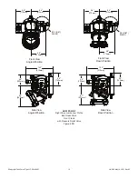
Top View
Angled Position
Top View
Down Position
Side View
Angled Position
Side View
Down Position
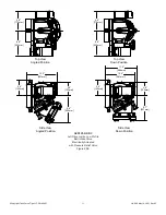
AXE1ST-NX-RC
Right Drive Jumbo Low Profile
Ball Intake Valve
Electrically Actuated
with Pressure Relief Valve