background image


Pagina 12 di 36


AD800E-STD.EN-06 - Subject to change without notice 


TFT DryAir 

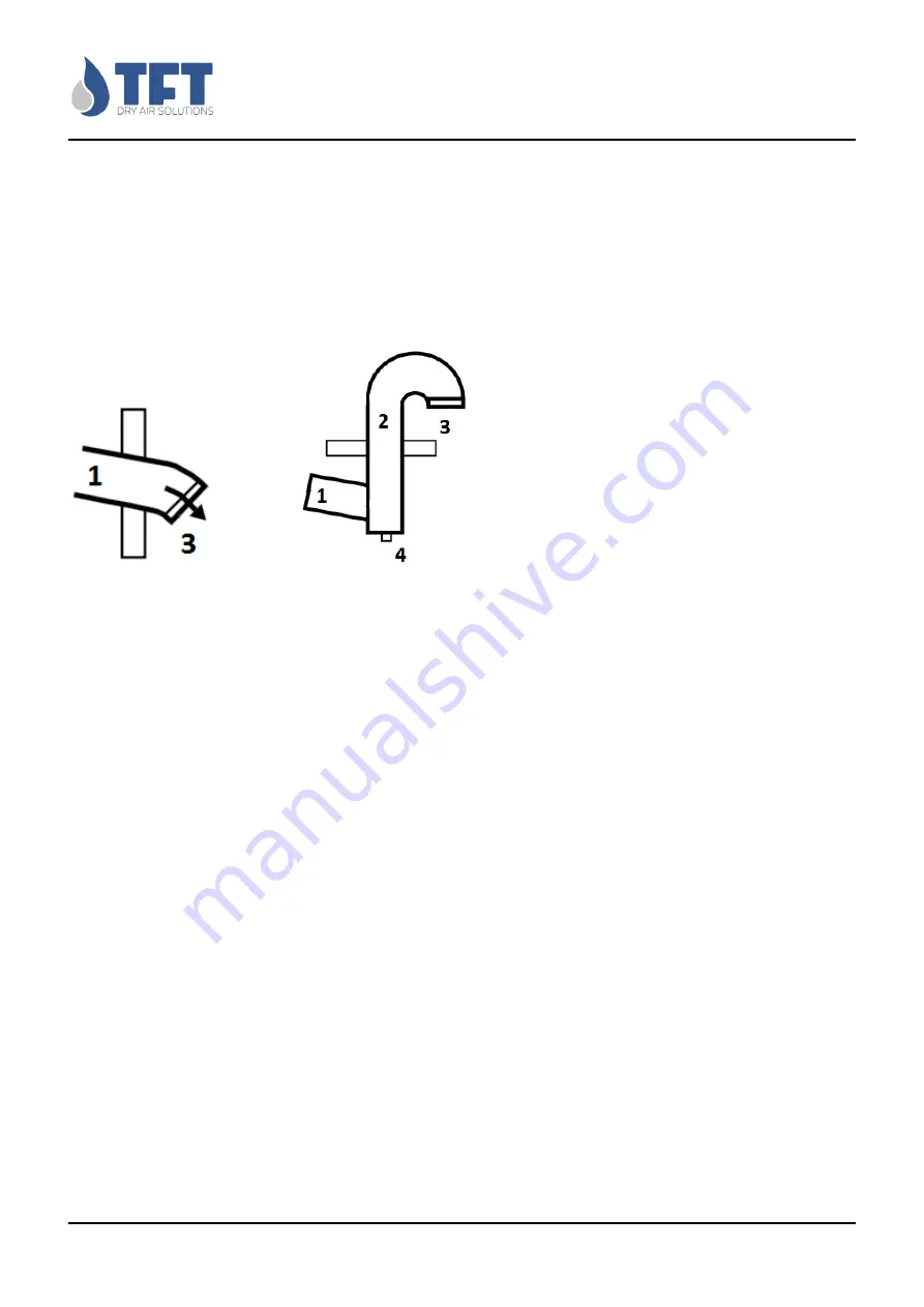
sloped to prevent any return of condensate inside the dehumidifier.


If the channel of the moist air is very 

long  or  needs  to  be  upwards,  realize  a  drainage  hole  of  5  mm  at  the  lowest  point  of  the  discharge 
channel.


It must be installed an air flow regulation damper.


Protect the channel output with a grid.


If 

there is a risk that the temperature external to the conduit is very low, it is mandatory to insulate piping 
to prevent the formation of condensation inside the duct. 


Horizontal 

Vertical 


Expulsion 

Expulsion 


1.


Slop down 

2.


Vertical expulsion of moist air 

3.


Wire mesh 

4.


Condensate drainage 


Specifications for the input channel of reactivation air 

This channel must be as short as possible. To prevent the entry of foreign bodies, protect the entrance 
channel with a grid. It is not necessary to isolate the pipe, which may be inclined downwards. In some 
installations, the reactivation air can be aspired from the room where the dehumidifier is installed and 
in this case it is not necessary any channel. 
 
It is advisable to install a damper on the reactivation circuit to allow a proper air flow calibration. 

Specifications for the channels of process air and dry air in case the dehumidifier is installed 
inside the room to be dehumidified    

In this case, it’s not necessary the addiction of aspiration channels for the process air; the installation of 
a protective grille is only required. The dry air produced must be ducted for the distribution inside the 
dehumidified room. 


Specifications for the channels of process air and dry air in case the dehumidifier is installed 
outside the room to be dehumidified 

In this case normally the inlet and outlet are channeled. 
When the suction of air takes place from the outside, the outlet of the air duct must be at a sufficient 
height  above  ground  level  in  order  to  prevent  the  suction  of  slag  and  dust. 

The  air  intake  must  be 

Summary of Contents for AD800E

Page 1: ...2018 TFT DryAir Dehumidifier AD800E Technical manual Unit 400Vac 3Ph 50Hz...

Page 2: ...nel 11 General instructions 11 Specification for the expulsion channel of moist air 11 Specifications for the input channel of reactivation air 12 Specifications for the channels of process air and dr...

Page 3: ...Spare Parts List 21 Component data 22 Electrical connections Preliminary Information Security 23 Electrical data 23 HOW TO CONNECT THE POWER SUPPLY 24 Electrical wiring 25 Description of adjustment c...

Page 4: ...off input power before opening any panel of the dehumidifier Allow the unit to cool down before maintenance work at least 15 minutes after turning off After power failure or mains disconnection an aut...

Page 5: ...te the warranty as will the use of non approved spare parts In order for the warranty to be valid the customer must scrupulously documented any repair and maintenance Rivolgersi sempre a TECNOFRIGO TU...

Page 6: ...ions that could generate a fulguration risk MOVING PARTS This symbol identifies hazards associated with moving parts HOT SURFACES This symbol identifies the presence of exposed hot surfaces that will...

Page 7: ...idifier works in a continuous process with two air streams process air and reactivation air As shown in the figure a honeycomb rotor dehumidifier consists of a honeycomb adsorbent rotor which is rotat...

Page 8: ...dsorbents are impregnated desiccants With the advanced silica gel rotor are no granules and no dusting It stops adsorbing moisture hen moisture is in equilibrium with the moisture in the passing or su...

Page 9: ...cal panel The electrical panel is located inside the unit Switches and indicators of operation are located outside the dehumidifier Possibility of operation The mode selector on the outside of the deh...

Page 10: ...cal regulations Do not get close and do not insert any objects into moving parts WORKERS HEALTH AND SAFETY The operator s workplace must be kept clean tidy and free from objects that might hinder move...

Page 11: ...uct falls below the dew point of the ambient air If there is a risk of sub zero temperatures the ducts must be insulated The high rate of humidity of the air issued by the unit it could cause condensa...

Page 12: ...o isolate the pipe which may be inclined downwards In some installations the reactivation air can be aspired from the room where the dehumidifier is installed and in this case it is not necessary any...

Page 13: ...meters from the exhaust duct of the moist air The ducts must be designed so as to prevent the infiltration of rain or snow in the dehumidifier The dehumidifier aspires the dehumidified air by the envi...

Page 14: ...he dehumidifier to the electricity grid through the general switch and switch the main switch ON and check for the voltage at the terminal L N or L1 L2 L3 of the dehumidifier 8 Start the dehumidifier...

Page 15: ...may differ from one installation to another Improper maintenance can result in decreased performance Filters The dehumidifier is equipped with two separate filters one for the process air and one for...

Page 16: ...FT is required to validate the full warranty Inspection During installation or when you need to work on the unit you must strictly follow the rules reported on this manual follow the instructions on t...

Page 17: ...agents that could damage it Take away and leave to the site manager any keys providing access to the control panel Unpacking The packaging may be dangerous for operators It is advisable to leave the...

Page 18: ...teral panels and the cover In the case of handling by forklift truck put a spacer between the security structure of the unit and the forks of the lift to avoid damaging to the panels In the case of ha...

Page 19: ...too high the rotor is stationary malfunction of reactivation coil check fans and motors check the flow rates and the dampers check the engine and the belt check the reactivation coil The dehumidifier...

Page 20: ...olt Ph Hz 400 3 50 Auxiliary power 24 V Connection Outlet Process Air 200 mm Connection Inlet Process Air 250 mm Connection Outlet Wet Air 160 mm Connection Inlet Reactivation Air 160 mm Weight 145 kg...

Page 21: ...recommended Comment Motordrive Motor a gear 230V 1Ph 50Hz 3g min grease for low temperature 1 1 Belt rotor V Sezione trapezoidale 1 Tensioning device 1 Process fan R2E250 RB06 01 1 Reactivation fan R2...

Page 22: ...BM Rotek Model SGM65 30 Speed g min 1775 2700 3 0 3 6 Power kW 0 165 0 085 11 VA Voltage V 230 230 230 Frequency Hz 50 60 50 60 50 60 Ampere A 1 3 0 38 0 015 Power factor Cos n a n a n a Protection cl...

Page 23: ...ed to the unit The power cables must be protected upstream against the effects of short circuit and overload by an appropriate device complies with regulations and laws The section of the cables must...

Page 24: ...T DryAir HOW TO CONNECT THE POWER SUPPLY To supply electrical power to units AD remove the top panel use the special cable in the rear or side panel and connect the power cord to the terminal block in...

Page 25: ...Pagina 25 di 36 AD800E STD EN 06 Subject to change without notice TFT DryAir Electrical wiring See attached diagrams...

Page 26: ...ing it indicates absolute humidity or value DewPoint calculated fixed it indicates absolute humidity or DewPoint value read by the probe Indication cooling air pre and or post treatment Indication hea...

Page 27: ...Only vis Y_3P Indication value position of 3 point burner valve Only vis InrH Indication value relative humidity absolute humidity or DewPoint C g Kg Only vis HAbS Indication value of absolute humidi...

Page 28: ...Setting the set point of pre treatment temperature Function disabled with parameter CF03 0 C 10 0 St06 Differential set point of pre treatment temperature the differential works all on one side above...

Page 29: ...3 Electrical third step 3 steps 4 Electrical PWM control 5 Steam PWM control with converter 6 Throttle adjustment with 3 points 7 Gas adjustable on off on off burner reg High heat low heat 8 Steam Wa...

Page 30: ...o termostatati e controllati mediante la sonda di regolazione On Il primo gradino rimane fisso mentre tutti gli altri sono termostatati e controllati mediante la sonda di regolazione Il primo gradino...

Page 31: ...corresponding probe CF01 3 and CF08 0 No action Automatic A03 Alarm configuration You have enabled the display of the value of post treatment without enabling the corresponding probe CF01 and CF05 7 0...

Page 32: ...Pagina 32 di 36 AD800E STD EN 06 Subject to change without notice TFT DryAir...

Page 33: ...i 36 AD800E STD EN 06 Subject to change without notice TFT DryAir RESET alarms press the ESC key for about 3 seconds on the terminal display LED or put the AUTO 0 MAN 0 and bring it back to its previo...

Page 34: ...itioned in the fully closed is 0 while the fan continues to operate If the parameter FA01 OFF with the open contact of the first step step1 it will also stop the ventilation the fan of reactivation an...

Page 35: ...Pagina 35 di 36 AD800E STD EN 06 Subject to change without notice TFT DryAir Notes...

Page 36: ...to change without notice TFT DryAir By TECNOFRIGO TUSCANY srl Via J F Kennedy 25 27 29 56020 Capanne Z Ind Fontanelle Pisa Tel 39 0571467351 Fax 39 0571469217 e mail info tecnofrigo it info tftdryair...

Reviews: