16
EC
Hydro
Midsize
Make all adjustments with the engine shut off, spark
plug wire disconnected and mower drive disengaged.
FIXED CUTTERDECK HEIGHT OF CUT
The cutting height is determined by the position of
the blades in relation to the wheels. Variation to this
height may be made at THREE points. (See Height
of Cut Chart on Page 13 or Height of Cut decal lo-
cated under belt cover to set desired cutting height.)
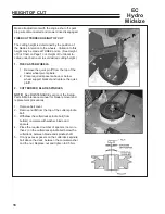
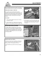
1. THE CASTER WHEELS
1. Remove the quick pin
P
from the top of the
caster wheel pivot spindle.
2. Place required spacers above or below
wheel support bracket and replace the quick
pin
P
.
2. CUTTERDECK BLADE SPINDLES
NOTE:
See MAINTENANCE section of the Setup,
Parts & Maintenance manual for blade removal and
replacement procedures.
1. Remove belt cover.
2. Remove nut
N
from the top of the cutter spindle
bolt.
3. Withdraw the cutterdeck spindle bolt (from
bottom) complete with washer, blade
and
spacers
4. Place the required number of spacers (no more
than 2) on the cutterdeck spindle bolt below the
cutterdeck, between blade and spindle shaft.
5. Fit any excess spacers on the cutterdeck spindle
bolt above the deck, between the conical washer
and the nut. Replace nut and tighten to 95 Nm.
HEIGHT OF CUT


