


1802 Bending Table
Greenlee / A Textron Company
4455 Boeing Dr. • Rockford, IL 61109-2988 USA • 815-397-7070
6
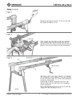
Select the proper size pipe support pins to be used:
• 3/4" diameter pin with 880 bender
• 1" diameter pin with 777 and 883 benders
• 1-1/2" diameter pin with 884 and 885 benders
Pipe support pin “A” is placed in bender frame hole that
corresponds to the size of conduit to be bent. Place
bender on table bed near end, opposite idler gear. Move
chain crank bracket forward to match the conduit size
holes in frame with like holes in bender bracket. Insert
pipe support pin “B” into brackets, bender frame, and
pipe support. When fully assembled, pipe support pin
“A” should be approximately 1" from leg support.
Note: Pipe support pins are optional equipment with
this unit and not furnished by the manufacturer.
Attach loose end of drive chain to pipe vise unit. Then
place chain around idler gear and chain crank gear.
Reposition idler gear to tighten drive chain, as it must be
tight for proper operation. Bending table is now ready
for bending radii up to 36" and with the Greenlee 884 or
885 bender in outer pipe support holes.
Note: To bend 36" radii or larger, chain extension kit
50214136 must be added to the standard drive chain.
This kit is required when using Greenlee 777 and 880
benders in the outer most position and Greenlee 884
and 885 benders in 3" pipe support position and lower.
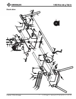
Chain Crank
Pipe Vise
Idler Gear
Pipe Support
Pin “A”
Pipe Support
Pin “B”
Chain Crank Unit
Bender
Pipe Support
Bender
Bracket
Setup
(cont’d)
Figure 6
Figure 7
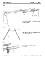
CHECK ALL SCREWS TO BE SURE THEY ARE TIGHT.
In some instances, when extra long radii bends are required, the length of bending table
at left end can be extended by adding 24" conduit couplings.


