1802 Bending Table
Greenlee / A Textron Company
4455 Boeing Dr. • Rockford, IL 61109-2988 USA • 815-397-7070
5
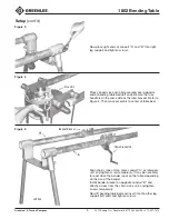
Place conduit vise and roller assembly over opposite
end of bending table bed (left end). Be sure that vise
handle is on the same side as the idler bracket. Refer to
Figure 2. Then move assembly to center of table bed.
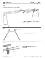
Now place right ends of conduit “A” and “B” into right
leg support and tighten screws.
Vise Unit
Setup
(cont’d)
Figure 3
Figure 4
Bender Bracket
Chain Crank Unit
Left End
Align chain crank unit on same conduit “A” as idler gear
unit, and tighten screw temporarily. It may be necessary
to reset when the bender is put on the table, depending
on the size of the bender.
Install bender bracket on opposite conduit “B” and
directly across from the chain crank unit, and tighten
screws temporarily.
Now lift bending table bed and insert into the other leg
support (left end), and tighten screws.
Figure 5


