background image

Hardware Setup

www.ti.com

24

SBOU123A – March 2012 – Revised September 2016

Submit Documentation Feedback

Copyright © 2012–2016, Texas Instruments Incorporated

XTR108EVM-USB Evaluation Board and Software Tutorial

3.8

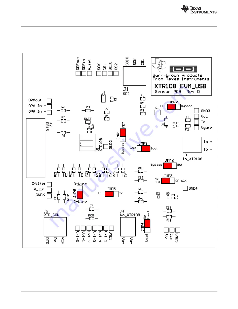
XTR108EVM-USB Sensor Board Default Jumper Settings

Figure 16

shows the default XTR108EVM-USB Sensor Board jumper configuration.

Table 19

summarizes

the default jumper configuration. For more information about the jumpers on the Sensor Board, see

Table 17

.

Figure 16. XTR108EVM-USB Sensor Board Default Jumper Settings

Summary of Contents for XTR108

Page 1: ...a parts list for the EVM Contents 1 Overview 4 2 Hardware Overview 6 3 Hardware Setup 16 4 Software Setup 25 5 Software Overview 26 6 General Operating Tips 47 7 Hardware Documentation 48 8 Appendix 52 List of Figures 1 Hardware Included With the XTR108EVM USB 5 2 XTR108EVM USB Hardware Setup 6 3 XTR108EVM USB Block Diagram 7 4 XTR108EVM USB Interface Board Connectors and Jumpers 8 5 XTR108EVM USB...

Page 2: ...000 RTD 53 39 RSET Circuitry 54 40 RLIN Circuitry 54 41 Linearity Correction Method 55 42 Linearity Improvement 55 List of Tables 1 XTR108EVM USB Kit Contents 5 2 Related Documentation 6 3 Multimeter Connect Pinout 9 4 J1 Pinout 15 Pin Female DSUB 9 5 J2 Pinout Vo_XTR108 9 6 J3 Pinout Io_XTR108 10 7 J4 Pinout Loop Supply 10 8 J5 Pinout 25 Pin Female DSUB 10 9 J6 Pinout 25 Pin Male DSUB 11 10 J7 Pi...

Page 3: ...16 Texas Instruments Incorporated XTR108EVM USB Evaluation Board and Software Tutorial 28 XTR108EVM USB Interface Board Bill of Materials 50 29 XTR108EVM USB Sensor Board Bill of Materials 51 30 Standard RTD Equations 56 31 Mnemonic Commands 59 32 SPI Modes of Operation 60 33 General USB DAQ Commands 60 ...

Page 4: ...ion errors for RTDs resistive thermal devices and bridge sensors Overall system accuracy of 0 1 error relative to full scale output span or less is easily achievable using a two point calibration algorithm The XTR108EVM USB consists of three PCBs One board the USB DAQ Platform generates the digital signals required to communicate with the XTR108 The second board XTR108EVM USB Interface Board provi...

Page 5: ...f any component is missing It is highly recommended that you also check the XTR108 product folder to verify that you have the latest version of the related software Figure 1 Hardware Included With the XTR108EVM USB Table 1 XTR108EVM USB Kit Contents Quantity Item Description 1 USB DAQ Platform Digital communications board 1 XTR108EVM USB Interface Board XTR108EVM USB Interface Board with required ...

Page 6: ... the time of the writing of this document Newer revisions may be available from the TI web site at www ti com or contact the Texas Instruments Product Information Center Identify the document by both title and literature number Table 2 Related Documentation Document Literature Number USB DAQ Platform user s guide SBOU056 XTR108 product data sheet SBOS187 2 Hardware Overview Figure 2 shows the XTR1...

Page 7: ...rface Board also contains a network of signal controlled relays from the USB DAQ that handles the routing of all EVM input and output signals The Interface Board also includes a user configurable RTD emulator circuit that simulates the behavior of a RTD resistive thermal device using potentiometers and surface mount resistors Using the RTD emulator allows the user to more quickly achieve a deeper ...

Page 8: ...on Feedback Copyright 2012 2016 Texas Instruments Incorporated XTR108EVM USB Evaluation Board and Software Tutorial 2 2 Interface Board Overview Figure 4 shows the location of all XTR108EVM USB Interface Board connectors and jumpers Figure 4 XTR108EVM USB Interface Board Connectors and Jumpers ...

Page 9: ...tion I F Current output measurement connection 2 2 1 2 J1 15 Pin Female DSUB Table 4 shows the signals connected to J1 on the Interface Board J1 is the connection for all input and output signals between the Interface Board and Sensor Board Table 4 J1 Pinout 15 Pin Female DSUB Pin Name Description 1 SPI_DIO SPI data input output 2 SPI_SCK SPI clock 3 SPI_CS1 SPI chip select 4 RCM RCM common mode r...

Page 10: ... loop power supply 2 2 1 6 J5 25 Pin Female DSUB Table 8 shows the signals connected to J5 on the Interface Board J5 is used to connect the USB DAQ control signals to the Interface Board Table 8 J5 Pinout 25 Pin Female DSUB Pin Name Description Used 1 NC No connection No 2 CTRL1 Control signal 1 Yes 3 CTRL2 Control signal 1 Yes 4 CTRL3 Control signal 1 Yes 5 CTRL4 Control signal 1 Yes 6 CTRL5 Cont...

Page 11: ...ADS2 negative input No 9 I2C_SCK I2 C clock No 10 I2C_SDA I2 C data No 11 ONE_WIRE One wire communication line No 12 I2C_SDA_ISO I2 C data isolated No 13 I2C_SCK_ISO I2 C clock isolated No 14 XTR LOOP Current loop high side input No 15 XTR LOOP Current loop low side input No 16 INA INA negative input No 17 VDUT Selectable 3 3 V or 5 0 V power supply No 18 VCC 5 0 V power supply Yes 19 15V 15 V pow...

Page 12: ...r Default Description JMP1 POT_RTD This jumper selects which resistor string is used for the RTD emulator minimum scale output Set the jumper to the POT_RTD position to use potentiometers POT1 and POT2 Set the jumper to the R_RTD position to use surface mount resistors R22 R24 not installed by default JMP2 POT_RTD This jumper selects which resistor string is used for the RTD emulator mid scale out...

Page 13: ...ntation Feedback Copyright 2012 2016 Texas Instruments Incorporated XTR108EVM USB Evaluation Board and Software Tutorial 2 3 Sensor Board Overview Figure 5 shows the location of all XTR108EVM USB Sensor Board connectors and jumpers Figure 5 XTR108EVM USB Sensor Board Connectors and Jumpers ...

Page 14: ...al loop power supply to the Sensor Board and to connect the XTR108 current output to an external ammeter Table 14 J3 Pinout Io_XTR108 Pin Name Description 1 IO Low side loop power supply and current output from the XTR108 2 IO High side loop power supply and current output from the XTR108 2 3 1 4 J4 Vo_XTR108 Table 15 shows the signals connected to J4 on the Sensor Board J4 is used to connect the ...

Page 15: ... jumper selects whether to connect or disconnect a load resistor RL not installed by default from the voltage output of the XTR108 Set the jumper to the NO LOAD position when using current output mode Set the jumper to the LOAD position when using voltage output mode optional JMP5 IOUT This jumper selects between the current output or voltage mode charge pump input at the XTR108 I_IN pin Set the j...

Page 16: ...f the surface mount components have pin sockets associated with them These pin sockets allow the replacement of a surface mount component with a through hole component The pin sockets provide good contact with the leads of a component without solder thus enabling quick reconfiguration of the board for many different XTR108 designs as shown in Figure 6 Figure 6 Pin Socket Mechanical Description 3 H...

Page 17: ... connect the two PCBs together gently push on both sides of the 25 pin D SUB connectors as shown in Figure 7 Make sure that the connectors are completely pushed together because loose connections may cause intermittent operation Figure 7 Connecting the USB DAQ Platform to the XTR108EVM USB Interface Board Next connect the XTR108EVM USB Sensor Board to the XTR108EVM USB Interface Board by gently pu...

Page 18: ...ected connect a 6Vdc to 9Vdc power supply to J5 or T3 of the USB DAQ platform A power cable is included that fits J5 Caution Be sure to observe correct polarity If connected properly the µC OK 3 3 V and VCC LEDs on the USB DAQ illuminate as shown in Figure 9 Always connect power before connecting the USB cable If you connect the USB cable before connecting the power the computer attempts to commun...

Page 19: ...time Typically the computer responds with a Found New Hardware USB Device pop up message The pop up message typically changes to Found New Hardware USB Human Interface Device shortly after This message indicates that the device is ready to be used The USB DAQ Platform uses the Human Interface Device drivers that are part of the Microsoft Windows operating system In some cases the Windows Add Hardw...

Page 20: ...b power supply to J4 on the Interface Board as shown in Figure 12 When operating in current output mode the loop supply input voltage range is 12 V to 24 V In general you must consider the power dissipated in the external transistor and the operating temperature of the transistor in order to determine the maximum loop voltage and current This calculation is determined in the XTR108 data sheet When...

Page 21: ... that routes the current output voltage output and RTD emulator signals to the multimeter connect terminals on the XTR108EVM USB Interface Board Any standard lab multimeter that supports dc voltage dc current and four wire resistance measurements is compatible with the XTR108EVM USB This EVM is designed and tested with the Agilent 34401A multimeter To properly connect the XTR108EVM USB Interface B...

Page 22: ...108EVM USB Evaluation Board and Software Tutorial 3 6 USB DAQ Platform Default Jumper Settings Figure 14 shows the default USB DAQ Platform jumper configuration In general these jumpers should not be changed For more information about the function of these jumpers refer to the USB DAQ Platform User s Guide Figure 14 USB DAQ Platform Default Jumper Settings ...

Page 23: ...ce Board jumper configuration Table 18 summarizes the default jumper configuration For more information about the jumpers on the Interface Board see Table 12 Figure 15 XTR108EVM USB Interface Board Default Jumper Settings Table 18 XTR108EVM USB Interface Board Default Jumper Settings Jumper Position Description JMP1 POT_RTD Use POT1 POT2 for the RTD emulator minimum scale output JMP2 POT_RTD Use P...

Page 24: ...VM USB Evaluation Board and Software Tutorial 3 8 XTR108EVM USB Sensor Board Default Jumper Settings Figure 16 shows the default XTR108EVM USB Sensor Board jumper configuration Table 19 summarizes the default jumper configuration For more information about the jumpers on the Sensor Board see Table 17 Figure 16 XTR108EVM USB Sensor Board Default Jumper Settings ...

Page 25: ...ws XP operating system OS with United States and European regional settings The software should also function on other Windows operating systems Please report any OS compatibility issues to the Precision Amplifiers E2E forum 4 2 XTR108EVM USB Software Installation Follow these steps to install the XTR108EVM USB software 1 Software can be downloaded from the XTR108EVM USB product folder or from the...

Page 26: ...iew Once the XTR108EVM USB starts up several SPI communications take place to initialize the Interface Board and read the XTR108 register values Refer to Figure 18 for a screen shot of how the software should appear if the EVM is functioning properly The actual values of the fields inside the XTR108 block diagram such as PGA gain or ILIN DAC Linearization may vary Figure 18 XTR108EVM USB Software ...

Page 27: ...ts Other indicators display the supporting circuitry values for the current configuration The remainder of this section provides an in depth explanation of the function of each group of controls and indicators in the Block Diagram tab All fields located internal to the XTR108 are controls that can be manipulated by the user but it is recommended that only advanced users make changes to the control...

Page 28: ...200 mA V approximately Table 20 shows the gain to transconductance relationship For voltage output applications the PGA can be set for rail to rail output for example VZERO 0 5 V and VFS 4 5 V The PGA section of the block diagram shows the PGA voltage gain setting in V V Table 20 PGA Gain Loop Transconductance and Input Full Scale Differential Voltage Voltage Gain V V Output Transconductance mA V ...

Page 29: ... uses the external resistor RLIN to convert voltage into current The ILIN DAC section of the block diagram shows the hexadecimal value of the linearization register register 14 The recommended value for the external resistor RLIN is also shown at the bottom of the block diagram 5 1 6 Overscale Underscale The XTR108 incorporates circuitry to set adjustable limits at the output in cases when the sen...

Page 30: ... 0 0 1 1 2 8125 V 22 2 mA 0 1 0 0 2 875 V 22 7 mA 0 1 0 1 2 9375 V 23 2 mA 0 1 1 0 3 0 V 23 7 mA 0 1 1 1 3 0625 V 24 2 mA 1 0 0 0 3 125 V 24 6 mA 1 0 0 1 3 1875 V 25 1 mA 1 0 1 0 3 25 V 25 6 mA 1 0 1 1 3 3125 V 26 1 mA 1 1 0 0 3 375 V 26 6 mA 1 1 0 1 3 4375 V 27 1 mA 1 1 1 0 3 5 V 27 6 mA 1 1 1 1 3 5625 V 28 1 mA Table 24 Underscale Threshold US2 US1 US0 VO Underscale Threshold IO Underscale Thres...

Page 31: ...lt into the XTR108EVM USB software also write new register values to the EEPROM so that post calibrated values are automatically loaded at power up The SPI Interface section of the block diagram shows whether the automatic EEPROM read back is enabled or disabled 5 1 8 Alarm Config The XTR108 Alarm Configuration register register 7 determines whether the XTR108 goes overscale or underscale for vari...

Page 32: ...ed XTR108 operating conditions Based on the user input the software calculates the appropriate values for the supporting circuitry and performs error checking to determine if the desired conditions exceed system capabilities This tab also allows the user to save a custom configuration as a model file that is used as the basis for calibration Figure 20 shows the Find Resistors tab with default valu...

Page 33: ... controls correspond to the values listed in Table 23 and Table 24 These controls automatically update the units mA or V to reflect the status of the Mode control 5 2 1 4 Channel Enable The XTR108 supports up to five input channel configurations allowing the same board design to be used for multiple input conditions Only one channel can be calibrated at a time The Channel Enable control allows the...

Page 34: ... error widen your temperature ranges slightly and click the Calculate Resistors button again Figure 21 RSET Error The XTR108EVM USB software also performs a linearity check as part of the Calculate Resistors functionality If the software predicts that a post calibrated error less than 0 1 of full scale is not possible a warning message is displayed as shown in Figure 22 This error is typically cau...

Page 35: ...le dialog box as shown in Figure 23 Enter a descriptive file name that contains the output span and some basic configuration information such as 4 20mA CH1 0 300C in the image below This naming allows for easy differentiation between model files when loading a file for calibration The default save location for model files is in the Model_files folder within the XTR108EVM USB install directory typi...

Page 36: ...form a two point calibration calculate the post calibrated error of the system and calibrate the overscale and underscale output values Figure 24 shows the Manual Calibration tab with default values The following sections explain the use of each section of the tab NOTE The XTR108EVM USB includes functionality to automatically control the Agilent 34401A Multimeter This functionality requires that t...

Page 37: ...Initialize the Set RTD_Min Set RTD_Mid and Set RTD_Max buttons are enabled and the calculated resistance values for each channel are displayed As shown in Figure 25 the resistance value of each RTD Emulator channel can be set by adjusting the trim pots of each channel with a small flat head screwdriver Figure 25 Adjust RTD Emulator Click the Set RTD_Min button to set the resistance of the RTD_Min ...

Page 38: ...econd Corrections button to perform the second corrections based on this measurement and write the updated configuration to the XTR108 and EEPROM 5 3 5 Step 5 Error Calculator The Error Calculator section allows the user to determine the error expressed as a percentage of full scale at minimum scale mid scale and maximum scale output levels Click the Set RTD Emulator to Minimum Scale button to rou...

Page 39: ...m scale mid scale and maximum scale Percent Error indicators should be less than or equal to 0 1 See Figure 26 for an example of a successful post calibration screen Figure 26 Manual Calibration Tab Post Calibration 5 3 8 Reset Calibration The Reset Calibration button can be clicked at any time in order to cancel the current calibration and reset the Manual Calibration tab to the initial state At ...

Page 40: ... completely automated calibration of the XTR108 using a previously saved model file The entire procedure takes less than a minute to complete and only requires the user to click one button Figure 27 shows the Automatic Calibration tab The following sections explain the use of each section of the tab NOTE Use of the Automatic Calibration tab requires that an Agilent 34401A multimeter be connected t...

Page 41: ...loaded into the software The XTR108EVM USB software automatically loads the most recent model file into memory at startup but a different model file can be selected by clicking the Load Model File button The path of the loaded model file is shown in the Model File indicator 5 4 3 Step 2 Select Channel Use the Channel to Calibrate control to select which channel should be calibrated Disabled channe...

Page 42: ...imum scale error after calibration is less than or equal to 0 1 the Status indicator displays the message Calibration successful Error 0 1 and the square status LED turns on bright green Figure 28 shows an example of a successful post calibration screen If the percentage of error after calibration is greater than 0 1 the Status indicator displays the message Calibration unsuccessful Error 0 1 and ...

Page 43: ...sters tab in the XTR108EVM USB software enables the user to view and edit the contents of each register internal to the XTR108 Similar to the Block Diagram tab it is recommended that only advanced users make bit level changes using this tab However for debugging purposes this capability can be extremely useful Figure 29 shows the Registers tab The actual values of each register may vary Figure 29 ...

Page 44: ...Settings The Save Register Settings button allows the user to save the current values of the register array as a csv file The default save location for register files is in the Register_files folder within the XTR108EVM USB install directory typically C Program Files XTR108EVM USB The Load Register Settings button allows the user to load a previously saved register file which can be useful for loa...

Page 45: ...e measurement and resistance measurement relays are disabled by circuit protection logic CTRL2 Enables voltage measurement relay When CTRL1 is enabled the voltage measurement and resistance measurement relays are disabled by circuit protection logic CTRL3 Enables resistance measurement relay When CTRL1 is enabled the voltage measurement and resistance measurement relays are disabled by circuit pro...

Page 46: ...all SPI communications The command lines follow the syntax of the tioScript mnemonic commands More information on the mnemonic commands is available in the Mnemonic Commands section Pressing the Clear button clears the strings displayed in the Debug Window until new communications take place Figure 31 Debug Window 5 6 3 About Window The About window as shown in Figure 32 lists the version build da...

Page 47: ...oltage by approximately 0 7 V To get an accurate idea of the XTR108 supply voltage while in this mode you should measure at the XTR108 VS pin 6 2 Charge Pump When the XTR108 is in voltage output mode a small negative voltage must be applied to the XTR108 IIN pin to prevent the input offset voltage of the XTR108 current output stage from turning on the output stage A simple discrete charge pump cir...

Page 48: ...lay7 D7 Relay 7 R16 510 R15 510 D4 Relay 4 R13 510 D3 Relay 3 R20 510 Relay3 Relay4 D1 Relay 1 R19 510 Relay1 D2 Relay 2 R18 510 Relay2 Note Relays Are Initially OFF A CTRL Logic Hi gh Turns On Each Relay Note SPI Data Input Connected to Data Output at Pins 24 25 Loop Loop Vo Vo Io Io XTR108 Sensor Board Connector Multimeter Connect Panasonic ON Panasonic Vcc GND VCC VCC VCC VCC VCC VCC VCC 1 12 3...

Page 49: ... R6 Iout Vo_XTR108 Io_XTR108 499 6 34k 12 1k Steward HZ0603 Steward HZ0603 Io Io Vo Vo Rz Rcm RTD Io Io Vo Vo Rz Rcm RTD SPI_SCK SPI_DIO SPI_CS1 SPI_SCK SPI_DIO SPI_CS1 BAV99RWT1 1SS355TE 17 Male SCK SDIO OPA In Vo Vo CS1 RTD Rz Rcm Io Io 1 2 3 J1 SPI SDIO SCK CS1 Note 100V cap V I 0 1 V I 1 2 V I 2 3 V I 3 4 V I 4 5 V I 5 6 Cfilter 7 Rlin 8 Vo 9 Iin 10 Iret 12 Io 11 Vs 13 Vgate 14 REFin 20 REFout...

Page 50: ...S2SS 4 5V K1 K2 K3_1 K3_3 K4 K8 LOW SIGNAL RELAYS PCB 1A 4 5VDC DPDT NON LATCHING SMD Panasonic Electric Works TXS2SS 4 5V 1 ULN2803 U1 IC DUAL TRANS ARRAY HV 18 SOIC Texas Instruments ULN2803ADW 3 BAT754S U2 U4 DIODE SCHOTTKY 30V 200MA SOT 23 NXP Semiconductors BAT754S 215 1 SN74AHC1G04 U5 IC SINGLE INVERTER GATE SOT23 5 Texas Instruments SN74AHC1G04DBVR 2 SN74AHC1G08 U6 U7 IC SGL 2IN POS AND GAT...

Page 51: ...Ltd RR0816P 1212 D 09C 1 6 34kΩ RVI RES 6 34K OHM 1 16W 5 0603 SMD Susumu Co Ltd RR0816P 6341 D 78H 1 100 0Ω RZ1 RES 100 OHM 1 10W 1 0603 SMD Panasonic ECG ERA 3AEB101V 0 OMIT RZ2 RZ5 RL R6 C2 C7 Omit not installed N A N A 1 1SS355TE 17 D1 DIODE SWITCH 90V 100MA SOT 323 Rohm Semiconductor 1SS355TE 17 1 BAV99 D2 DIODE SWITCH SS DUAL 70V SOT323 ON Semiconductor BAV99RWT1G 2 Ferrite F1 F2 FERRITE 300...

Page 52: ... describes the operation of key XTR108 functional blocks 8 1 1 Input MUX The primary function of the XTR108 input multiplexer MUX is to allow a single hardware module to function for multiple RTD ranges and types In the typical XTR108 configuration one MUX channel is used for the RTD and five other channels remain for different ranges RZ1 through RZ5 are used to the set the minimum temperature TMI...

Page 53: ...ion with the RTD at maximum temperature where TMAX 850 C At this point the differential input voltage to the PGA is equal to 186 mV the maximum value for this configuration Figure 37 XTR108 Input MUX Example TMAX 850 C PT100 RTD Figure 38 shows how the current sources can be programmed to accommodate different types of RTDs The previous example used a 100 Ω RTD or PT100 In this example the RTD typ...

Page 54: ...nd Software Tutorial 8 1 2 RSET The range of the IREF DAC that controls the current sources I1 and I2 is set by the external resistor RSET For example with a value of RSET 12 1 kΩ the range of IREF is 480 µA to 510 µA If RSET 121 kΩ the range of IREF becomes 48 µA to 51 µA The Find Resistors tab within the XTR108EVM USB software helps to determine the appropriate RSET value Figure 39 RSET Circuitr...

Page 55: ...ard and Software Tutorial 8 1 4 Linearity Correction Figure 41 illustrates how the XTR108 linearity correction works The RTD has a response that is approximately quadratic gray line The positive feedback of the input signal through the linearity DAC ILIN generates a response that is also approximately quadratic black line The two responses counteract each other to generate a linear output red line...

Page 56: ...rature RTDMIN medium temperature RTDMID and maximum temperature RTDMAX Pick an external zero resistor RZ that is the closest standard value to RTDMIN 1 A 3 9083E 3 B 5 775E 7 C 4 183E 12 R0 RTD value at 0 C typically 100 Ω or 1 kΩ and T temperature in C Table 30 Standard RTD Equations 1 If 200 C T 0 C If T 0 C Rt R0 1 A T B T2 C T3 T 100 C Rt R0 1 A T B T2 8 2 1 2 Relative Nonlinearity Calculate t...

Page 57: ...struments Incorporated XTR108EVM USB Evaluation Board and Software Tutorial 8 2 1 5 IZERO DAC Zero Offset Calculate the required IZERO DAC value 8 2 1 6 Calculate DAC Codes The IREF and IZERO DACs are controlled by registers 10 11 12 and 13 in the XTR108 Use the following equations to determine the values to be written to these registers N10 N11 N12 and N13 are decimal values that must be converte...

Page 58: ... VREF Appendix www ti com 58 SBOU123A March 2012 Revised September 2016 Submit Documentation Feedback Copyright 2012 2016 Texas Instruments Incorporated XTR108EVM USB Evaluation Board and Software Tutorial 8 2 2 2 IREF Registers Calculate the corrections for the IREF registers NOTE If the adjusted value for register 10 N10_A is outside of the possible range of 127 N10_A 128 then use the following ...

Page 59: ...rted to output current in order to satisfy the same sets of equations Use the following equation to convert output voltage to output current 8 4 Mnemonic Commands The USB DAQ platform uses a set of mnemonic commands to perform SPI communications to the XTR108EVM USB These commands are given in Table 31 Table 31 Mnemonic Commands Command Description SPI Always the first mnemonic in an SPI command C...

Page 60: ...lock idles high CPOL 1 Data are read by the USB DAQ on the clock rising edge Data are changed by the USB DAQ on the clock falling edge Data are sampled on the second clock edge CPHA 1 The USB DAQ also supports a set of generic commands used to enable or disable power supplies read from internal ADCs set the output of internal DACs and set the voltage of control pins The XTR108EVM USB uses the GPIO...

Page 61: ...ring the warranty period to the address designated by TI and that are determined by TI not to conform to such warranty If TI elects to repair or replace such EVM TI shall have a reasonable time to repair such EVM or provide replacements Repaired EVMs shall be warranted for the remainder of the original warranty period Replaced EVMs shall be warranted for a new full ninety 90 day warranty period 3 ...

Page 62: ... by Industry Canada to operate with the antenna types listed in the user guide with the maximum permissible gain and required antenna impedance for each antenna type indicated Antenna types not included in this list having a gain greater than the maximum gain indicated for that type are strictly prohibited for use with this device Concernant les EVMs avec antennes détachables Conformément à la rég...

Page 63: ... connecting any load to the EVM output If there is uncertainty as to the load specification please contact a TI field representative During normal operation even with the inputs and outputs kept within the specified allowable ranges some circuit components may have elevated case temperatures These components include but are not limited to linear regulators switching transistors pass transistors cu...

Page 64: ...F REMOVAL OR REINSTALLATION ANCILLARY COSTS TO THE PROCUREMENT OF SUBSTITUTE GOODS OR SERVICES RETESTING OUTSIDE COMPUTER TIME LABOR COSTS LOSS OF GOODWILL LOSS OF PROFITS LOSS OF SAVINGS LOSS OF USE LOSS OF DATA OR BUSINESS INTERRUPTION NO CLAIM SUIT OR ACTION SHALL BE BROUGHT AGAINST TI MORE THAN ONE YEAR AFTER THE RELATED CAUSE OF ACTION HAS OCCURRED 8 2 Specific Limitations IN NO EVENT SHALL T...

Page 65: ...esponsible for compliance with all legal regulatory and safety related requirements concerning its products and any use of TI components in its applications notwithstanding any applications related information or support that may be provided by TI Buyer represents and agrees that it has all the necessary expertise to create and implement safeguards which anticipate dangerous consequences of failur...

Reviews: