Software Setup
25
SBOU123A – March 2012 – Revised September 2016
Copyright © 2012–2016, Texas Instruments Incorporated
XTR108EVM-USB Evaluation Board and Software Tutorial
Table 19. XTR108EVM-USB Sensor Board Default Jumper Settings
Jumper
Position
Description
JMP1
FET
Enable FET sub regulator
JMP2
FET
Enable FET sub regulator
JMP3
IOUT
Current-output mode
JMP4
NO LOAD
Load resistor disconnected
JMP5
IOUT
Current-output mode
JMP6
BYPASS
Bypass SPI clock buffer on charge pump
JMP7
NO CLK
Disable charge pump
JMP8
2-WIRE
Select two-wire RTD
4
Software Setup
This section describes how to install the XTR108EVM-USB software.
4.1
Operating Systems for XTR108EVM-USB Software
The XTR108EVM-USB software is tested on the Microsoft Windows XP operating system (OS) with
United States and European regional settings. The software should also function on other Windows
operating systems. Please report any OS compatibility issues to the
Precision Amplifiers E2E forum
.
4.2
XTR108EVM-USB Software Installation
Follow these steps to install the XTR108EVM-USB software:
1. Software can be downloaded from the
, or from the disk included with
the XTR108EVM-USB that includes a folder called
Install_software/
.
2. Find the file called
setup.exe
. Double-click the file to start the installation process.
3. Follow the on-screen prompts to install the software.
4. To remove the application, use the Windows
Add/Remove Software
control panel utility.
4.3
Starting the XTR108EVM-USB Software
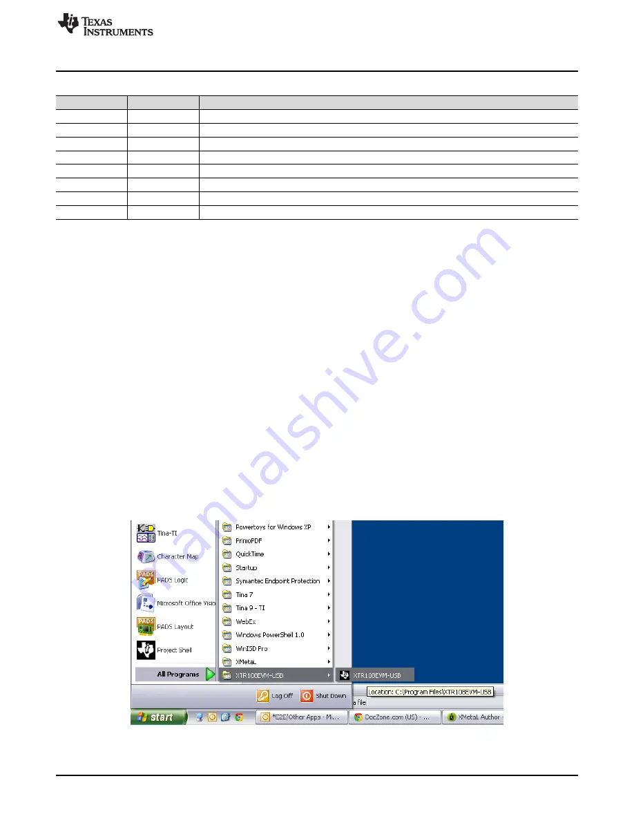
The XTR108EVM-USB software can be started through the Windows
Start
menu. Click
Start
→
All
Programs
→
XTR108EVM-USB
→
XTR108EVM-USB
to start the program, as shown in
Figure 17. Starting the XTR108EVM-USB Software


