Using the GUI
7.2
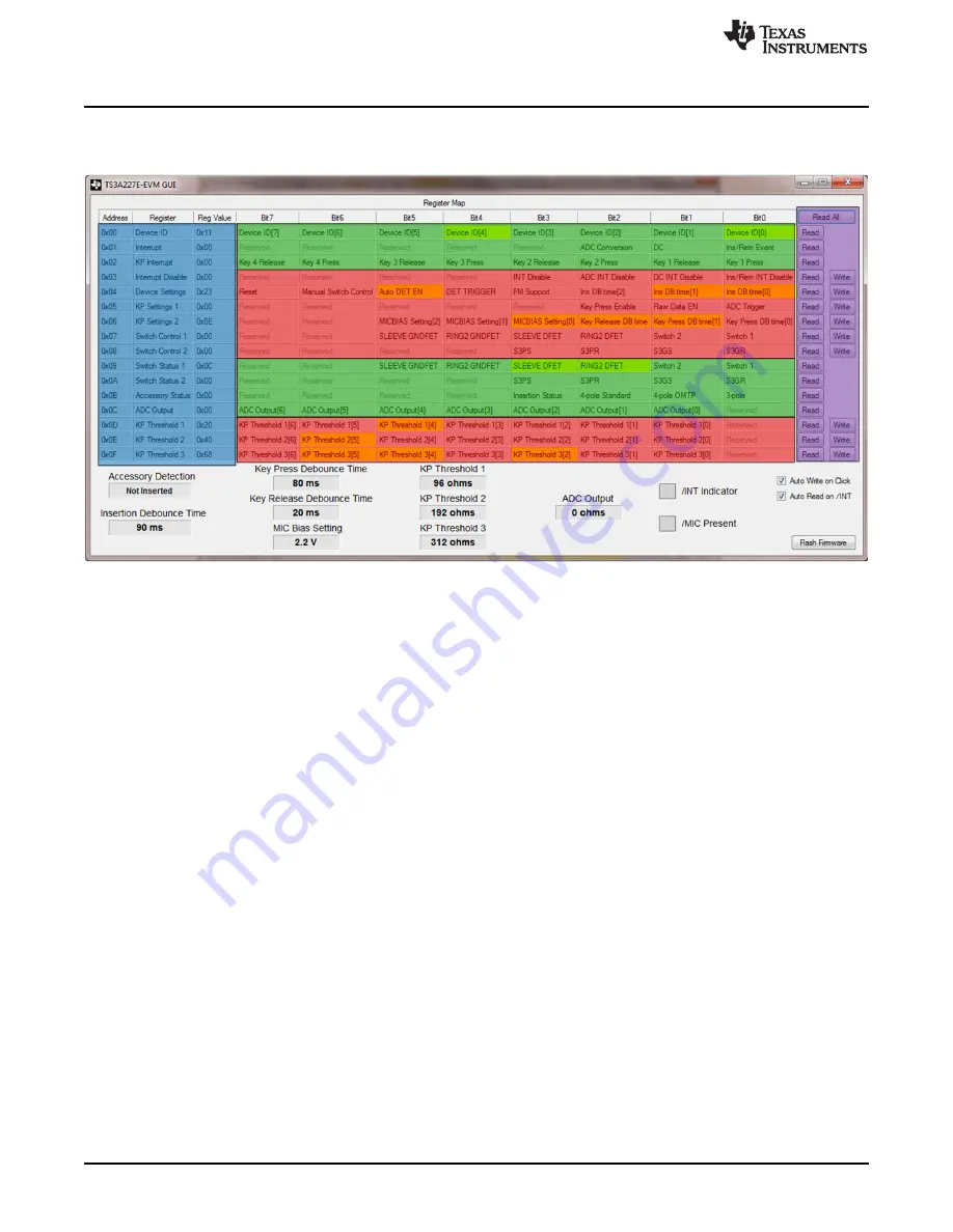
GUI Area Descriptions and Use
This section describes the various sections of the GUI.
shows the TS3A227E-EVM GUI.
Figure 17. TS3A227E-EVM GUI
•
The blue section of the GUI denotes the
Register Address
,
Register Name
, and the current stored
Reg
Value
at that register in Hex. These fields cannot be edited and clicking them has no effect.
•
The green section of the
Register Map
indicates Read-only registers. These values are only updated
with data from the MSP430 LaunchPad
•
The red section of the
Register Map
indicates Read/Write registers. Clicking on any bit of these
registers not labeled
Reserved
toggles that bit. If
Auto Write on Click
is checked, clicking on a bit also
sends a command to the MSP430 to write the value entered to the TS3A227E.
–
For example, if register 0x03 currently has the value 0x01 and bit 1 of that register is clicked, bit 1
toggles from a value of ‘0’ to a new value of ‘1’. The GUI then sends the new register value of 0x03
to the LaunchPad to write to the TS3A227E.
–
Bits that a colored in yellow are == 1. Bits that are colored gray are == 0.
•
The pink section of the GUI denotes the Read/Write buttons.
–
Clicking a
Read
button reads the value of the corresponding register it is adjacent to (for example,
clicking the top-most
Read
button reads register 0x01 and updates the GUI contents).
–
Clicking a
Write
button writes the currently shown value for the adjacent register in the GUI to the
TS3A227E.
–
Clicking the
Read All
button reads the entire register map and also updates the pin status.
14
TS3A227E EVM User's Guide
SLVUAD9 – December 2014
Copyright © 2014, Texas Instruments Incorporated


