49
SLOS743L – AUGUST 2011 – REVISED MARCH 2017
Product Folder Links:
Detailed Description
Copyright © 2011–2017, Texas Instruments Incorporated
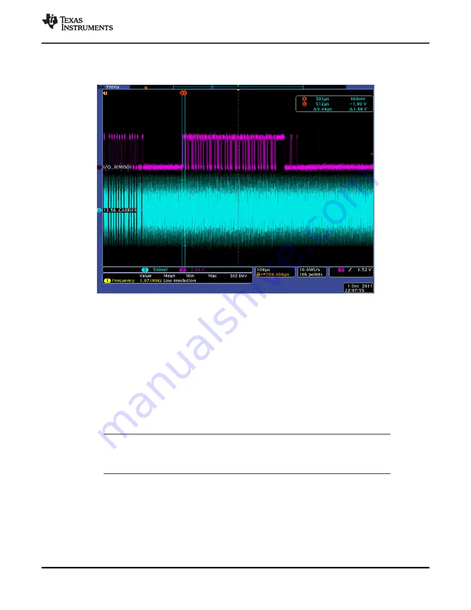
shows an example of what the developer should expect on the I/O_6 line during the RX
process while in direct mode 0.
Figure 6-32. RX Sequence on I/O_6 in DM0 (Analog Capture)
Step 7: Terminating Direct Mode 0
After the EOF is received, data transmission is over, and direct mode 0 can be terminated by sending a
Stop Condition (in the case of SPI, make the Slave Select go high). The TRF7970A is returned to default
state.
6.11 TRF7970A Initialization
To properly initialize the TRF7970A, perform these steps:
1. Raise the EN, EN2, and SS lines at the correct intervals after power up (for timing diagrams, see
and
2. Issue a Software Initialization direct command (0x03), followed by an Idle direct command (0x00) to
soft reset the TRF7970A.
NOTE
lists the initial register settings for the TRF7970A after the Software Initialization
command.
3. Delay 1 ms to allow the TRF7970A to fully process the soft reset.
4. Issue a Reset FIFO direct command (0x0F).
5. Write the Modulator and SYS_CLK Control register (0x09) with the appropriate application-specific
setting for the crystal and system clock settings.
6. (Optional) Write the Regulator and I/O Control register (0x0B) with the appropriate application-specific
setting.
7. Write the NFC Target Detection Level register (0x18) with the value of 0x00. For details on this
requirement, see the


