PCB Layout
www.ti.com
6
SBVU040 – February 2018
Submit Documentation Feedback
Copyright © 2018, Texas Instruments Incorporated
TPS7A10EVM-004 Evaluation Module
5
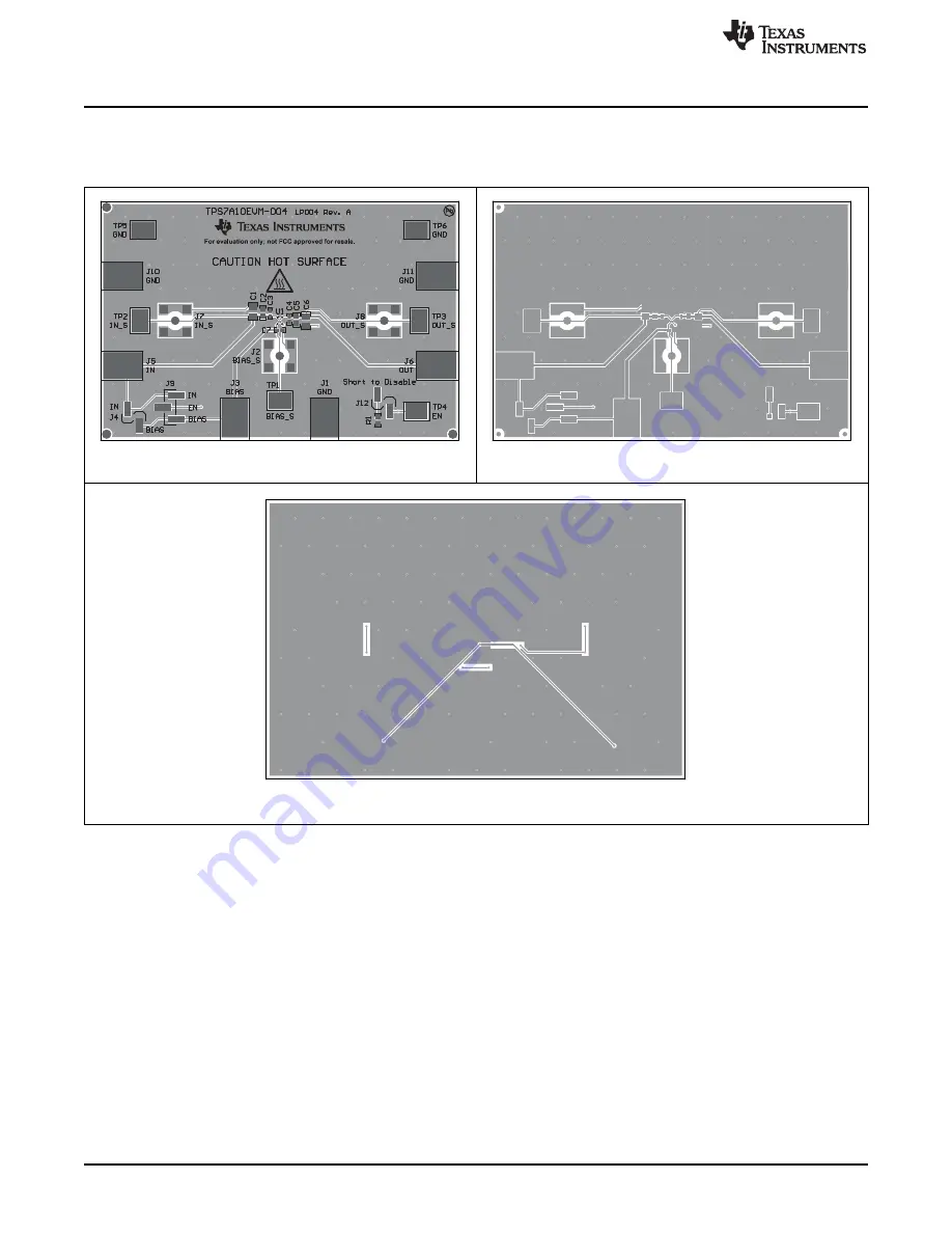
PCB Layout
Figure 1
to
Figure 3
show the PCB layout for this EVM.
Figure 1. Assembly Layer
Figure 2. Top Layer Routing
Figure 3. Bottom Layer Routing


