


EVM Details
12
SLVUBT0 – December 2019
Copyright © 2019, Texas Instruments Incorporated
TPS6594x-Q1 Evaluation Module
3.6
Connectors
In addition to J12 and the terminal connections, J32-J36 are SMA connectors for testing the buck
regulator outputs. These connectors are not populated.
Two load module connector footprints are provided, J16 and J17. The connector components are not
populated.
3.7
EVM Control, GPIO, and additional regulators
The EVM has a built-in USB interface based upon the MSP432E401Y (U3) to allow the GUI, from the host
computer, to communicate with the PMIC. The supply voltage required by the MSP432E401Y is generated
automatically by the TLV7103318 (U6) device which provides 3.3 V and 1.8 V from USB power, VBUS.
These voltages are available for supplying VIO_IN for the PMIC (selectable from J30). Two
SN74GTL2003 level shifters (U8, U9) are used in order to support the use case of the PMIC VIO_IN of 1.8
V (the MCU IO will always be 3.3 V). In addition to the level translators, the TS3A5018RSVR switch is
used to apply the pullup voltages to the I
2
C lines only when the EVM is a master (J37). The application of
the pullup resistors is for I
2
C mode only and is only intended for one board in a stack-up application. Note:
in the stack-up configuration only one board can have a valid VBUS voltage on the board. This means that
the master board can have a connected USB cable supplying VBUS or that VSYS can be connected to
VBUS through J15, see
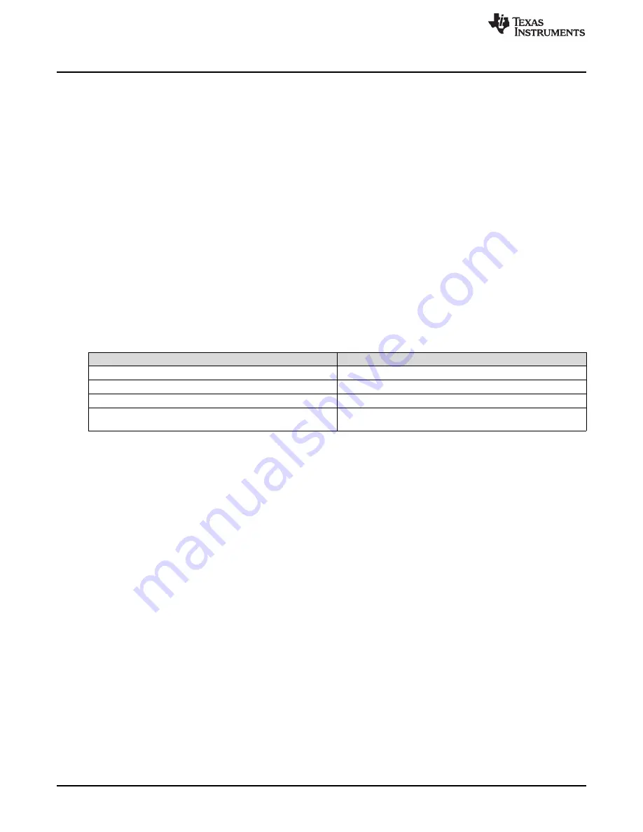
. The EVM has 4 LEDs to indicate board power, on or off, and some
select PMIC GPOs status. The signals are listed in
Table 10. EVM LED Indicators
LED Designator
Indication
D3
LED is on when EN_DRV is high.
D4
LED is on when nINT is low.
D5
LED is on when nRSTOUT is low.
D6
EVM power indicator. LED is on when VCCA is higher than 2.8
V.
4
Customization
The EVM, in conjunction with GUI tool, provides various degrees of customization. A couple of examples
are provided here which can be generalized to a number of functions.
4.1
Changing the Communication Interface
The default settings for communication with the PMIC is I
2
C. This default configuration for GPIO1 and
GPIO2 are the function settings SCL_I2C2 and SDA_I2C2, respectively.


