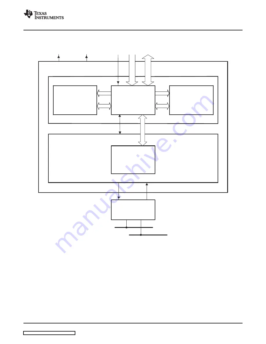
1.1.2 Block Diagram
32−Message
Mailbox RAM
4 X 32−Bit Words
for each mailbox)
Memory Management
Unit
CPU Interface,
Receive Control Unit,
Timer Management Unit
Control and status
registers
32
32
Message Controller
32
32
32
32
32
32
Enhanced CAN Controller
32
Controls
Address
Data
ECAN1INT
ECAN0INT
8
SN65HVD23x
3.3−V CAN Transceiver
CAN Bus
Communication
fers
A
buf
1.1.3 eCAN Compatibility With Other TI CAN Modules
www.ti.com
CAN Overview
Figure 1-1. eCAN Block Diagram and Interface Circuit
A
The communication buffers are transparent to the user and are not accessible by user code.
The eCAN module is identical to the “High-end CAN Controller (HECC)” used in the TMS470™ series
microcontrollers from Texas Instruments with some minor changes. The eCAN module features several
enhancements (such as increased number of mailboxes with individual acceptance masks, time stamping,
etc.) over the CAN module featured in 240x™ series of DSPs. For this reason, code written for 240x CAN
modules cannot be directly ported to eCAN. However, eCAN follows the same register bit-layout structure
and bit functionality as that of 240x CAN (for registers that exist in both devices) i.e., many registers and
bits perform exactly identical functions across these two platforms. This makes code migration a relatively
easy task, more so with code written in C language.
SPRU074F – May 2002 – Revised January 2009
Architecture
11


