


Software Overview
12
SLOU464A – March 2017 – Revised October 2017
Copyright © 2017, Texas Instruments Incorporated
TAS6422-Q1 Evaluation Module
3.5.2
TAS6422 Settings on Device Monitor and Control Window
The TAS6422 Register Map window is for reference. Most of the register settings are done on the Device
Monitor and Control window
Click on “CONNECT” button on the bottom left corner of the TAS6422 EVM application window, see
. The LED next to the TAS6422 EVM changes from gray to green and the “CONNECT” button
changes to “DISCONNECT” button.
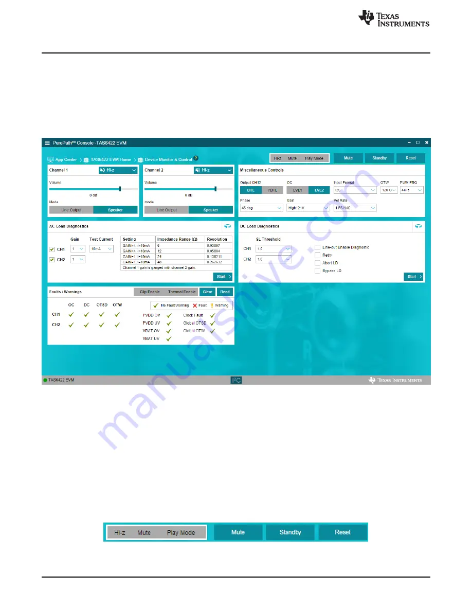
Click on the TAS6422 Device Monitor and Control box. The following window is displayed.
Figure 11. Device Monitor and Control Window
This window has 6 major sections: global control section, channel control section, other control section,
faults and warnings section, AC load diagnostics section and DC load diagnostics section.
3.5.2.1
Global Control Section
The Hi-z, Mute and Unmute buttons with the gray background controls all 4 channels at the same time.
When Hi-z is selected, all 4 channels are put in Hi-z. The display for each channel in the channel control
section will reflect these buttons selections.
The Mute Pin button is the GPIO pin controlling the mute function of the device.
The Standby button is the GPIO pin controlling the standby function of the device.
The Reset button is software reset. This will put the device back in default settings.
Figure 12. Global Control Section