Schematic, PCB Layout, and Bill of Materials
www.ti.com
18
SBOU181 – October 2016
Submit Documentation Feedback
Copyright © 2016, Texas Instruments Incorporated
OPT3006EVM User's Guide
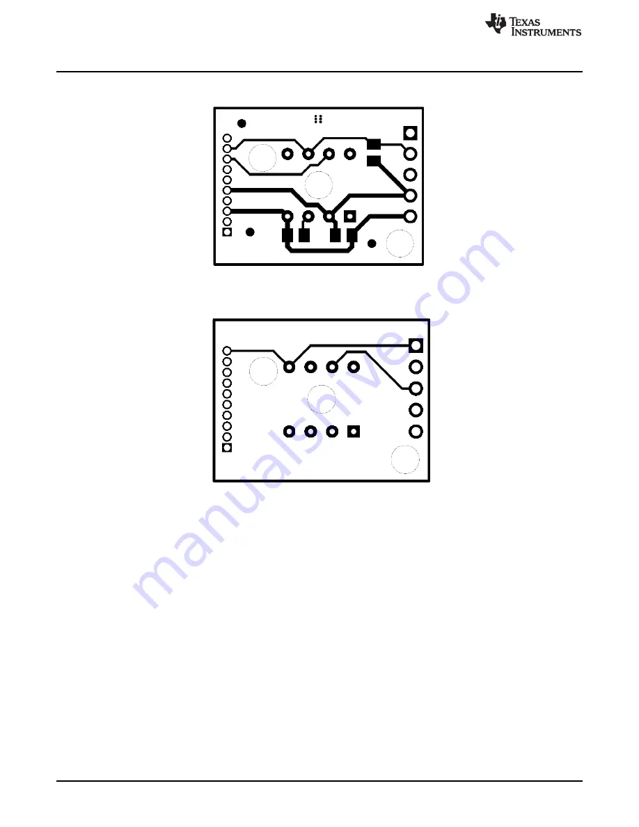
Figure 25
and
Figure 26
show the top and bottom PCB layers of the EVM, respectively.
Figure 25. PCB Top Layer
Figure 26. PCB Bottom Layer


