VCC
GND
Refer to U1 Datasheet/EVM User's Guide for recommended operating conditions
VCC
High
Low
GND
VEE
VCC
VEE
GND
GND
GND
GND
GND
GND
GND
Place all components connected to U1 pins 2 and 6 close to the respective pins.
Remove planes under all traces and components connected to U1 pins 2 and 6.
Do NOT remove planes under pad of R2 connected to U1 pin1.
Place on bottom under U1 pins 5 and 7.
GND
VEE
9
2
3
4
5
6
7
8
1
V+
V-
OPA818IDRGR
U1
2.2uF
C1
2.2uF
C4
0.01uF
C7
0.22uF
C2
0.22uF
C5
0.01uF
C3
0.01uF
C6
1000 ohm
L1
1000 ohm
L2
J6
VCC
J7
GND
J8
VEE
TP1
VCC
TP2
GND
TP3
VEE
1
2
3
4
5
J1
In-
1
2
3
4
5
J2
In+
1
2
3
4
5
J3
PD AC
DNP
1
2
3
4
5
J5
Out
1
2
3
J4
PD DC
49.9
R5
DNP
0
R8
0
R9
0
R10
0
R3
49.9
R4
49.9
R1
49.9
R6
301
R2
71.5
R7
DNP
EVM Specifications
2
SBOU222A – April 2019 – Revised February 2020
Copyright © 2019–2020, Texas Instruments Incorporated
OPA818DRGEVM Evaluation Module
2.2
Input and Output Connections
The OPA818DRGEVM is equipped with SMA connectors to connect the EVM to signal generators and
analysis equipment. As shipped, the EVM is configured for a noninverting gain of 7 configuration and split-
supply operation with terminals for connecting to 50-
Ω
test equipment. For best results, route all signals to
and from the EVM with cables that have a characteristic impedance of 50
Ω
. See the
,
schematics, and layouts for details on how to reconfigure for other gain configurations.
3
EVM Schematic, Board Layout, and Bill of Materials (BOM)
This section provides a complete schematic diagram, board layouts, and a bill of materials for the
OPA818DRGEVM.
3.1
EVM Schematic
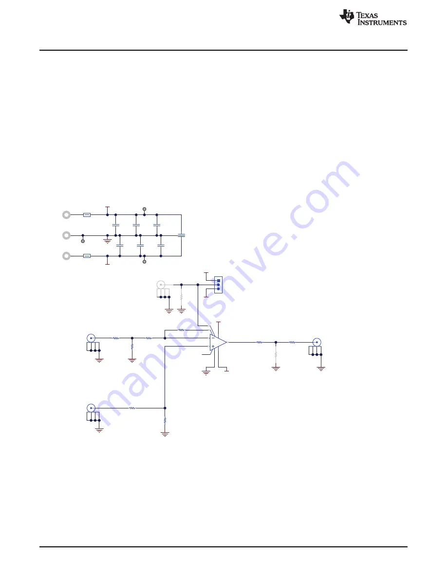
shows a schematic diagram for the OPA818DRGEVM.
Figure 1. OPA818DRGEVM Schematic


