


Public Version
PRCM Basic Programming Model
www.ti.com
To support the I
2
C communication with external power ICs, the slave address of the power ICs must be
configured in the voltage controller registers. The voltage controller can support two slave addresses to
control VDD1 and VDD2 independently, from two different power ICs. At least one valid slave address
is required to communicate with a power IC.
NOTE:
The slave address for the following depends on the configured slave address of the power
IC:
•
[6:0] SA0
•
[22:16] SA1
2. Set voltage configuration register addresses.
The addresses of the voltage configuration registers of the power ICs are set in the corresponding bit
fields. The voltage controller can support addresses of two different voltage configuration registers
(belonging to same or different power ICs).
[7:0] VOLRA0
Depend on the characteristics of the connected
power ICs.
[23:16] VOLRA1
3. Set command configuration register addresses.
The addresses of the command configuration registers of the power ICs are set in the corresponding
bit fields. The voltage controller can support addresses of two different command configuration
registers (belonging to same or different power ICs).
[7:0] CMDRA0
Depend on the characteristics of the connected
power ICs.
[23:16] CMDRA1
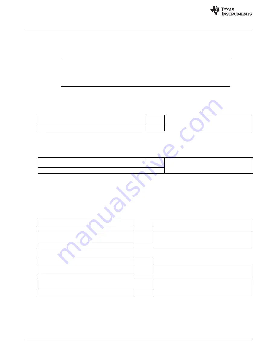
4. Set configuration pointers for the VDD channels.
The configuration pointers allow the selection of one of four configurations for each voltage channel
(VDD1 and VDD2):
•
Two slave I
2
C interfaces (slave address)
•
Two voltage configuration registers
•
Two command configuration registers
•
Two power-mode voltage levels
[16] SA1
Slave address pointer (SA1 for VDD2, and SA0 for VDD1)
[0] SA0
[17] RAV1
Voltage configuration register address pointer (RAV1 for
VDD2, and RAV0 for VDD1)
[1] RAV0
[18] RAC1
Command configuration register address pointer (RAC1 for
VDD2, and RAC0 for VDD1)
[2] RAC0
[19] RACEN1
Select voltage or command configuration register for FSM
commands (RACEN1 for VDD2, and RACEN0 for VDD1)
[3] RACEN0
[20] CMD1
Command voltage level selection pointer (CMD1 for VDD2,
and CMD0 for VDD1)
[4] CMD0
5. Configure I
2
C.
At power-on reset, the I2C4 is in HS mode. In HS mode, a master code value must be configured for
the preamble I
2
C HS transmission. If the external power ICs do not support I
2
C HS mode, the interface
can be switched to fast/standard (F/S) mode. By default, a repeated-start operation for communication
is enabled. If necessary, it can be disabled.
For more information, see
, I
2
C.
440
Power, Reset, and Clock Management
SWPU177N – December 2009 – Revised November 2010
Copyright © 2009–2010, Texas Instruments Incorporated