Transceiver
Device
Transceiver
USB
UTMI+
UTMI
sideband
reencode
sidebands
sidebands
Software-driven
usb-016
L3 inter-
connect
USB controller
USB controller
UTMI
to
serial
USBTLL
module
Other
IC
Serial
IF
Serial
IF
Public Version
High-Speed USB Host Subsystem
www.ti.com
NOTE:
The device does not support 4-pin bidirectional signaling using DAT/SE0 signals.
22.2.2.4.2 Sideband Signals for Serial Modes
Serial interfaces only carry the USB data information. Sideband control and status (respectively, to/from
the transceiver/TLL or to the bus lines themselves) require additional signals, which are usually
implemented in a case-by-case, ad hoc way.
•
Sideband control examples: FS/LS (slew rate control), transceiver suspend, connect (D+/D– pullup),
pulldown enable, VBUS drive, etc.
•
Sideband status example: VBUS level (VBUS valid, session valid, session end), etc.
•
Sideband signal implementations: Dedicated lines (one per sideband information bit), serial bus +
interrupt line with register-mapped control/status (I
2
C, UART, etc.)
and
show system integration for sideband signals for two logically identical
USB connections: One in transceiver configuration, and one in TLL configuration. Although the sideband
(purple) arrows are all oriented from controller to transceiver in the two figures, the sideband information
flow is bidirectional (that is, it flows from controller to transceiver [control] but also from transceiver to
controller [status]).
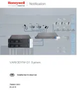
shows the transceiver configuration, where each side connects the sideband signals to its
own transceiver. On the device (containing the USBTLL module), the sideband is decoded/re-encoded.
The sideband signals available at the device boundary (and the USBTLL module) are decoded from the
standard UTMI+ interface.
•
Sideband output signals from the USBTLL module (speed, suspend, puen, etc.)
•
The software-driven VBUS reporting procedure is described in
, VBUS
Management in Serial Transceiver Configurations.
Figure 22-18. Serial Interface Sideband Integration - Transceiver Configuration
shows the TLL configuration, where both transceivers are actually emulated inside the
USBTLL module.
•
The transceiver of the local controller (left) is working with the sideband information to/from the UTMI+
port. This is internal to the USBTLL module.
•
The transceiver of the remote controller (right) must communicate with its controller, located on another
IC. This is done in two ways:
–
Sideband input signals at the TLL module boundary (tllpuen, tlldrvvbus, tllvbusvalid, etc.)
3250
High-Speed USB Host Subsystem and High-Speed USB OTG Controller
SWPU177N – December 2009 – Revised November 2010
Copyright © 2009–2010, Texas Instruments Incorporated