


uart-001
Device
UART1
(UART)
UART3
(UART/IrDa)
MPU subsystem
MPU INTC
IVA2.2 subsystem
IVA2.2 INTC
eDMA
sDMA
32
32
uart1_tx
uart1_rx
uart1_rts
uart1_cts
uart2_tx
uart2_rx
uart2_rts
uart2_cts
uart3_tx/uart3_tx_irtx
uart3_rx/uart3_rx_irrx
uart3_rts/uart3_rts_sd
uart3_cts/uart3_cts_rctx
2
2
2
UART1.IRQ
UART3.IRQ
UART2
(UART)
UART
.DMA_RX/TX
2
UART2.IRQ
UART1.DMA_RX/TX
UART3.DMA_RX/TX
L4-Core
UART4
(UART)
32
uart4_tx
uart4_rx
2
UART4.IRQ
UART4.DMA_RX/TX
32
L4-Per
Public Version
UART/IrDA/CIR Overview
www.ti.com
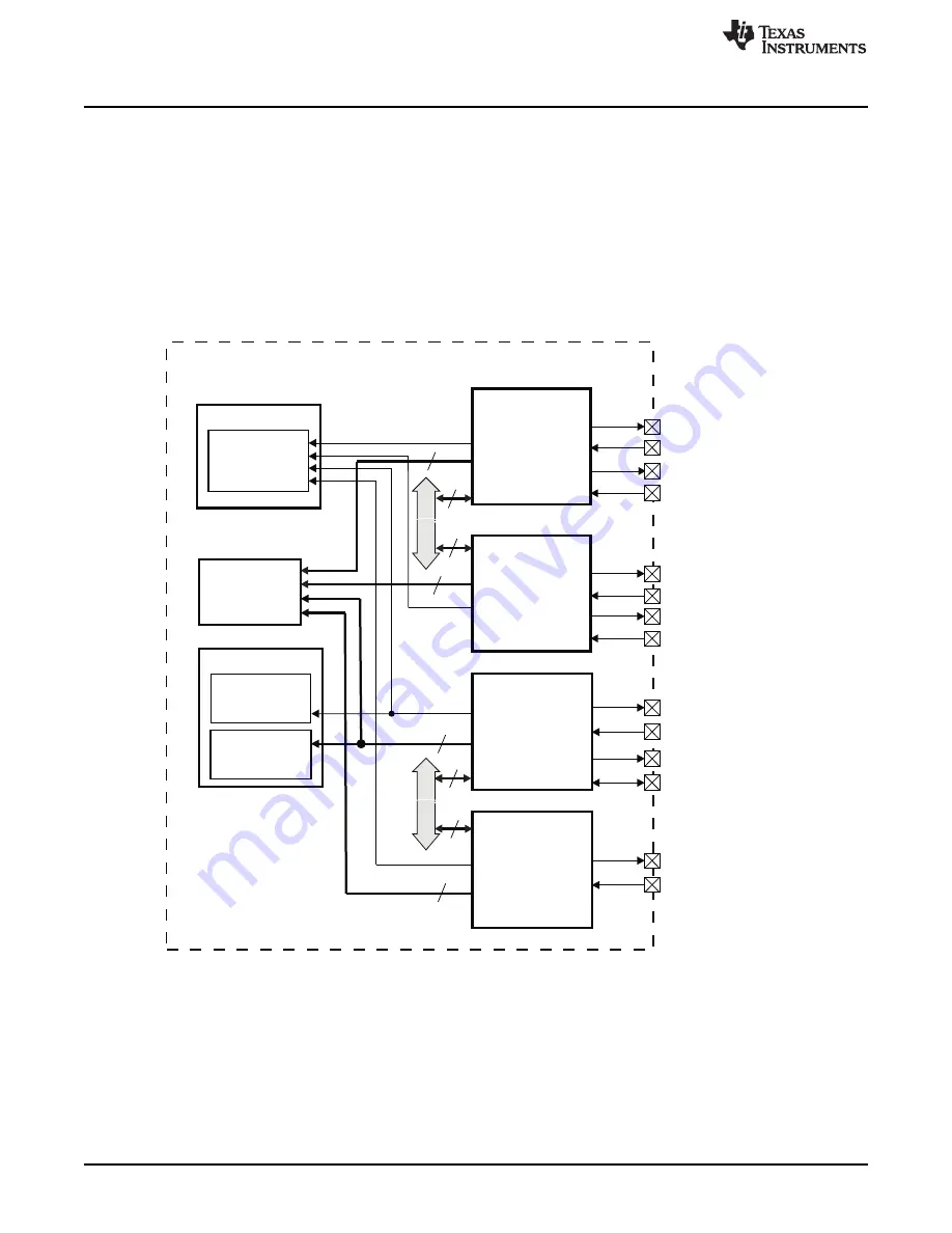
19.1 UART/IrDA/CIR Overview
The device contains three universal asynchronous receiver/transmitter (UART) devices controlled by the
microprocessor unit (MPU) (see
):
•
Three UART-only modules, UART1, UART2 and UART4 are pinned out for use as UART devices only.
UART1 and UART2 must be programmed by setting the UARTi.
[2:0] MODE_SELECT field
to one of the three UART operating modes.
•
UART3, which adds infrared communication support, is pinned out for use as a UART, infrared data
association (IrDA), or consumer infrared (CIR) device, and can be programmed to any available
operating mode.
Figure 19-1. UART Module
19.1.1 UART Features
The UARTs (UART1, UART2, UART3, UART4 when in UART mode) include the following key features:
•
16C750 compatibility
•
64-byte FIFO for receiver and 64-byte FIFO for transmitter
•
Programmable interrupt trigger levels for FIFOs
•
Baud generation based on programmable divisors N (N = 1 ... 16,384) operating from a fixed functional
clock of 48 MHz
Oversampling is programmed by software as 16 or 13; thus, the baud rate computation is either:
2870
UART/IrDA/CIR
SWPU177N – December 2009 – Revised November 2010
Copyright © 2009–2010, Texas Instruments Incorporated


