


Start
condition (S)
1
2
7
8
9
ACK
1
2
8
9
ACK
MSB
Acknowledgment
signal from
receiver
Stop
condition (P)
Acknowledgment
signal from
receiver
i2c _sda
i
i2c _scl
i
i2c-004
Data line stable
Data valid
Data change
allowed
i2c-005
Public Version
www.ti.com
HS I
2
C Environment
17.2.1.3 HS I
2
C Typical Connection Protocol and Data Format
17.2.1.3.1 HS I
2
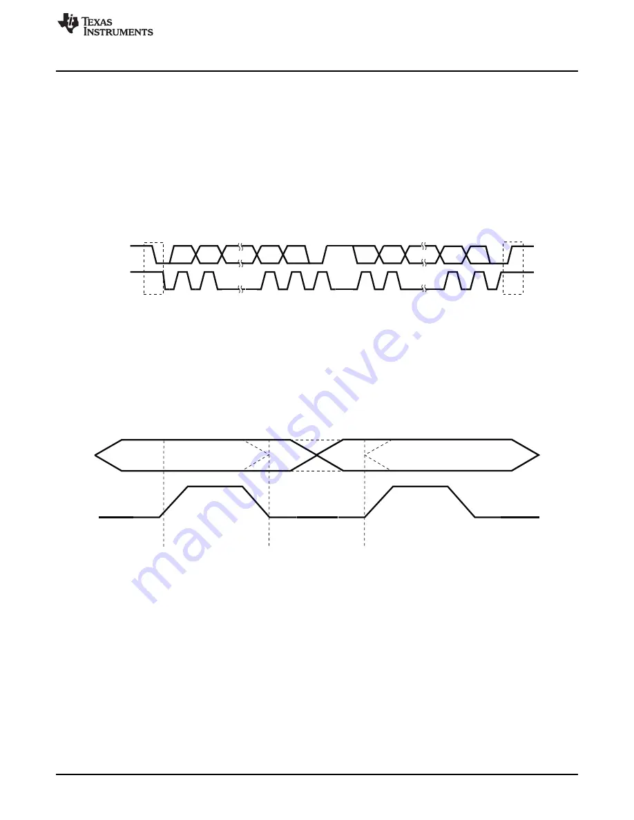
C Serial Data Format
The HS I
2
C controller operates in 8-bit word data format (byte write access supported for the last access).
Each byte transmitted or received on the serial data line (i2ci_sda) is 8 bits long. The number of bytes that
can be transmitted or received is not restricted. The data is transferred with the most-significant bit (MSB)
first. In receiver mode, each byte is followed by an acknowledge bit from the HS I
2
C.
shows a
typical HS I
2
C communication format.
Figure 17-4. HS I
2
C Serial Data Transfer
17.2.1.3.2 HS I
2
C Data Validity
The data on the serial data line must be stable during the high period of the clock i2ci_scl. The high and
low states of the data line can change only when the clock signal on the serial clock line is low.
is an example of data validity requirements.
Figure 17-5. HS I
2
C Bit Data Validity Transfer on the I
2
C Bus
17.2.1.3.3 HS I
2
C Start and Stop Conditions
The HS I
2
C module generates start (S) and stop (P) conditions when it is configured as a master.
•
An S condition is a high-to-low transition on the i2ci_sda line while i2ci_scl is high.
•
A P condition is a low-to-high transition on the i2ci_sda line while i2ci_scl is high.
The bus is considered busy after the S condition (the I2Ci.
[12] BB bit is 1 to indicate that the
bus is busy) and free after the P condition (the I2Ci.
[12] BB bit is 0 to indicate that the bus is
free).
shows the waveforms that occur during an S and a P condition.
2771
SWPU177N – December 2009 – Revised November 2010
Multimaster High-Speed I
2
C Controller
Copyright © 2009–2010, Texas Instruments Incorporated


