Device
System control module
Off values
MUXMODE
OFFENABLE
FORCEOFFMODEEN
0
1
PRCM
CONTROL_PADCONF_OFF
IO_CTRL
C
O
N
T
R
O
L
_
P
A
D
C
O
N
F
_
X
IO_PAD
SYS_OFF_MODE
Device
modules
Functional signal
values
scm-010
Public Version
SCM Functional Description
www.ti.com
13.4.4.4 System Off Mode
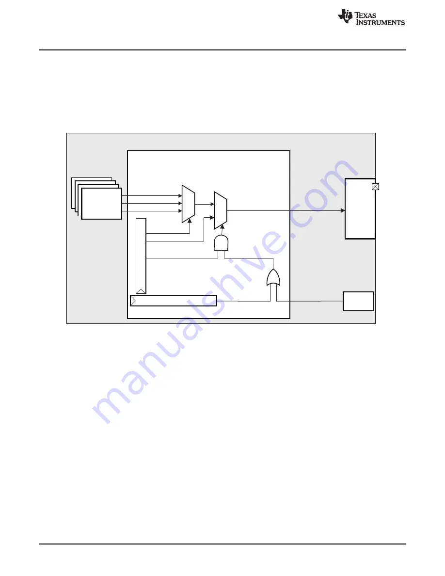
When system off mode is active (SYS_OFF_MODE = 0b1 from the PRCM module or the
CONTROL.
[0] FORCEOFFMODEENABLE bit = 0b1), the off mode values
field CONTROL.
overrides the pad state when OFFENABLE bit CONTROL.
is set.
shows the off mode pad control.
Figure 13-9. Off Mode Pad Control Overview
If off mode is active and the OFFENABLE bit is set to disable, the pad keeps the AND value of the
configuration (I/O, pullup/pulldown) it had before going into off mode:
•
For an input, the pad is isolated and the pull remains active.
•
For an output, the value is latched before going into off mode, to drive the same value in off mode
For more information about off mode, see
, Power, Reset, and Clock Management.
For more information about the preliminary settings that must be done before performing OFF <-> ON
transitions, see
, Off Mode Preliminary Settings.
13.4.4.4.1 Save-and-Restore Mechanism
Before going to off mode there is a context saving of the device. The save-and-restore mechanism saves
the pad configuration registers (in the CORE power domain) in a WKUP power domain memory (physical
addresses 0x4800 2600 to 0x4800 29FC) before going to off mode, and restores those registers when
returning from off mode. This mechanism uses the dedicated wake-up interface between the core control
module and the wake-up control module.
The save mechanism in the pad configuration registers is activated by setting the STARTSAVE bit
CONTROL.
[1]. When all pad configuration registers have been saved to the
wake-up memory, the status SAVEDONE bit CONTROL.
CONTROL_GENERAL_PURPOSE_STATUS
[0]
is set. In smart-idle mode, the idleAck is returned when the save process is complete.
When returning from off mode, the registers are restored after the PRCM module asserts the
START_RESTORE signal. The SCM returns a RESTORE_DONE signal to the PRCM module when the
restore process completes.
2464
System Control Module
SWPU177N – December 2009 – Revised November 2010
Copyright © 2009–2010, Texas Instruments Incorporated


