*Power from
Debugger
or External
J3
V+
J13
Debugger
JTAG
eZ-FET
J10
J12
External
VCC
GND
GND
J9
J2
Bypass
Use
Charge
J11
Super
Cap
External
J4
J5
VCC
GND
GND
J1
Current
MSP430FR5969
target and
BoosterPack
Target
MSP430FR5969
Device
Measure
Super Cap Charging
Configuration
J3
V+
J13
Debugger
J10
J12
External
VCC
GND
GND
J9
J2
Bypass
Use
Charge
J11
Super
Cap
J4
J5
VCC
GND
GND
J1
Current
MSP430FR5969
target and
BoosterPack
Target
MSP430FR5969
Device
Measure
Super Cap Running
Standalone Configuration
Hardware
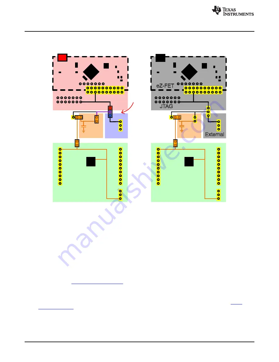
Figure 14. Super Cap Power Configuration – Charging and Running Standalone
2.4.5.3
Disabling the Super Cap
To disable the super cap, change J2 to "Bypass," and remove jumper J11 to prevent additional current for
charging the super cap. With these two jumper selections, the super cap is completely disconnected from
the system.
2.5
BoosterPack Plug-in Module Headers
The BoosterPack headers allow for a variety of applications to be created by plugging BoosterPacks onto
the LaunchPad. BoosterPacks cover a wide range of possible applications including wireless connectivity,
environmental sensing, and LCD displays. Leverage the growing BoosterPack ecosystem to rapidly
prototype nearly any application with the LaunchPad rapid prototyping platform. Available BoosterPacks
can be found at
The FR5969 LaunchPad adheres to the 20-pin LaunchPad pinout standard. A standard was created to aid
compatibility between LaunchPad and BoosterPack tools across the TI ecosystem.
The 20-pin standard is compatible with the 40-pin standard used by other LaunchPads like the
. This allows some subset of functionality of 40-pin BoosterPacks to be used with 20-pin
LaunchPads.
20
MSP430FR5969 LaunchPad™ Development Kit (MSP
‑
EXP430FR5969)
SLAU535B – February 2014 – Revised July 2015
Copyright © 2014–2015, Texas Instruments Incorporated


