


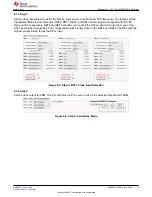


6.1.3 Step 3
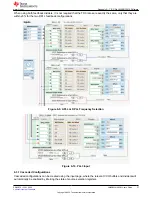
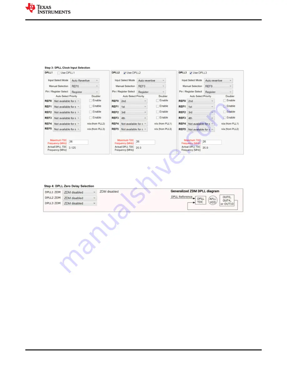
Set the clock input select mode for the DPLLs, input priority, and maximum TDC frequency. The recommended
Input Select Mode is
Auto Revertive
. REF0, REF1, REF2, and REF3 shown below correspond with IN0, IN1,
IN2, and IN3, respectively. REF4 and REF5 priorities can be set if the DPLLs input will be fed from one of the
APLL post divider frequencies. The corresponding APLL is listed next to the REF4 and REF5. The REF with the
highest priority will be fed as the DPLL input.
Figure 6-3. Step 3: DPLL Clock Input Selection
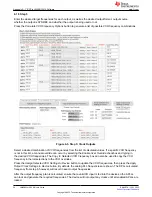
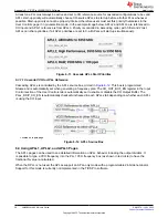
6.1.4 Step 4
Set the clock output for ZDM. The PLL will drive the PLL source mux for the selected output set for ZDM.
Figure 6-4. Step 4: Zero Delay Mode
Appendix A - TICS Pro LMK5B33414 Software
SNAU279 – JULY 2022
LMK5B33414EVM User's Guide
33
Copyright © 2022 Texas Instruments Incorporated


