


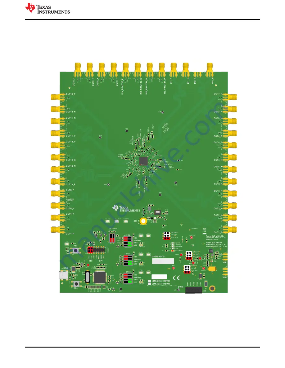
shows the jumper position with red markings.
shows the DIP switch positions in either
green boxes (for ON) or red boxes (for OFF) in the appropriate location.
OUT9_P
OUT9_N
OUT8_N
OUT8_P
IN3_N
IN3_P
IN2_N
IN2_P
IN1_N
IN1_P
IN0_N
IN0_P
OUT10_P
OUT10_N
OUT11_N
OUT11_P
OUT12_P
OUT12_N
OUT13_N
OUT13_P
OUT0_P
OUT0_N
OUT1_N
OUT1_P
OUT7_P
OUT7_N
OUT6_N
OUT6_P
OUT4_P
OUT4_N
OUT5_N
OUT5_P
OUT3_P
OUT3_N
OUT2_N
OUT2_P
VIN1
VIN2
Figure 1-1. LMK5B33414EVM Default Setting of Jumpers and DIP Switches
Introduction
SNAU279 – JULY 2022
LMK5B33414EVM User's Guide
3
Copyright © 2022 Texas Instruments Incorporated


