background image

www.ti.com

List of Figures

2-1.

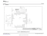
LM8330EVM Schematic Sheet1

..........................................................................................

7

2-2.

LM8330EVM Schematic Sheet2

..........................................................................................

8

2-3.

LM8330EVM Schematic Sheet3

..........................................................................................

9

2-4.

LM8330EVM Top Layer

..................................................................................................

10

2-5.

LM8330EVM Bottom Layer

..............................................................................................

11

3-1.

LM8330EVM GUI Installation Files

......................................................................................

14

3-2.

LM8330EVM GUI Install

..................................................................................................

15

3-3.

LM8330 GUI Initial Screen

...............................................................................................

16

3-4.

LM8330 GUI Open Success Screen

....................................................................................

16

3-5.

LM8330 GUI Open Error Screen

........................................................................................

17

3-6.

LM8330 GUI Close Screen

...............................................................................................

17

3-7.

LM8330 Initialization Example

...........................................................................................

18

3-8.

LM8330 GUI Keypad Test

................................................................................................

19

3-9.

LM8330 GUI Keypad Test Passed Example

..........................................................................

19

3-10.

LM8330 GUI Keypad Test Failed Example

............................................................................

20

List of Tables

1-1.

Device and Package Configurations

.....................................................................................

4

2-1.

Test Point Descriptions

.....................................................................................................

6

2-2.

Bill of Materials

.............................................................................................................

12

3

SNVU166 – FEBRUARY 2013

List of Figures

Submit Documentation Feedback

Copyright © 2013, Texas Instruments Incorporated


Summary of Contents for LM8330EVM

Page 1: ...Using the LM8330EVM Evaluation Module User s Guide Literature Number SNVU166 FEBRUARY 2013 ...

Page 2: ...Attached 6 2 3 Input Output Connector Description 6 2 4 Test Point Connectors 6 2 5 Schematics 7 2 6 Layout 10 2 7 Bill of Materials 12 3 GUI Configuration and Description 14 3 1 GUI Installation 14 3 2 GUI Functionality 15 3 2 1 Control Access 15 3 2 2 Initialization and LED Control 18 3 2 3 I2C Byte Access 18 3 2 4 LM8330 Registers 18 3 2 5 Keypad Status 18 3 2 6 Keypad Test 19 4 Related Documen...

Page 3: ... 4 LM8330 GUI Open Success Screen 16 3 5 LM8330 GUI Open Error Screen 17 3 6 LM8330 GUI Close Screen 17 3 7 LM8330 Initialization Example 18 3 8 LM8330 GUI Keypad Test 19 3 9 LM8330 GUI Keypad Test Passed Example 19 3 10 LM8330 GUI Keypad Test Failed Example 20 List of Tables 1 1 Device and Package Configurations 4 2 1 Test Point Descriptions 6 2 2 Bill of Materials 12 3 SNVU166 FEBRUARY 2013 List...

Page 4: ...2 C The LM8330EVM is a USB powered device with no external power supply required 1 1 List of Hardware Items for Operation To operate the LM8330EVM the following items are required The LM8330EVM Standard type A to type B mini USB cable PC with Windows XP Win7 or later operating system installed The LM8330EVM contains a USB to I2 C convertor MSP430F5529 USB ESD Protection LDOs Level Shifters and the...

Page 5: ...cure try a different USB port If the problem persists try rebooting the PC If the problem still persists try a different USB cable If these steps did not solve the problem contact TI technical support for help Run the LM8330EVM GUI software and follow the instructions for the GUI refer to Chapter 3 1 4 Hardware Uninstall Instructions Unplug the EVM from the USB port to uninstall the hardware from ...

Page 6: ...LM8330 J3 Input is the USB input connector This connector provides USB data communication 5V Power In and ground GND connections J4 Input Output is the I2 C input output connector This connector provides access to the I2 C SCL and SDA signals for monitoring from an external device 2 4 Test Point Connectors Test point connectors TP1 through TP4 allow the users to verify internal power rails on the ...

Page 7: ... ti com Schematics 2 5 Schematics Figure 2 1 LM8330EVM Schematic Sheet1 7 SNVU166 FEBRUARY 2013 EVM Configuration and Description Submit Documentation Feedback Copyright 2013 Texas Instruments Incorporated ...
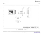
Page 8: ...Schematics www ti com Figure 2 2 LM8330EVM Schematic Sheet2 8 EVM Configuration and Description SNVU166 FEBRUARY 2013 Submit Documentation Feedback Copyright 2013 Texas Instruments Incorporated ...
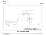
Page 9: ...www ti com Schematics Figure 2 3 LM8330EVM Schematic Sheet3 9 SNVU166 FEBRUARY 2013 EVM Configuration and Description Submit Documentation Feedback Copyright 2013 Texas Instruments Incorporated ...
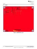
Page 10: ...Layout www ti com 2 6 Layout Figure 2 4 LM8330EVM Top Layer 10 EVM Configuration and Description SNVU166 FEBRUARY 2013 Submit Documentation Feedback Copyright 2013 Texas Instruments Incorporated ...

Page 11: ...www ti com Layout Figure 2 5 LM8330EVM Bottom Layer 11 SNVU166 FEBRUARY 2013 EVM Configuration and Description Submit Documentation Feedback Copyright 2013 Texas Instruments Incorporated ...
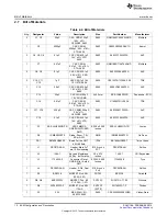
Page 12: ... NP0 0603 1 C18 0 1µF CAP CERM 0 1µF 0603 0603YC104JAT2A AVX 16V 5 X7R 0603 1 D1 SSF LXH305GD TR LED 3MM RA 0 250 x 0 250 SSF LXH305GD TR Lumex GREEN DIFFUSED inches SMD 1 D2 1SMB5922BTS Diode Zener 7 5V SMB 1SMB5922BT3G On Semi 50 mA 3W 1 FB1 BK1608HS600 T Bead Ferrite SMT 1206 BK1608HS600 T Taiyo Yuden 60Ω 800mA 1 J1 PEC07DAAN Header Male 2x7 0 100 inch x PEC07DAAN Sullins pin 100mil spacing 2X7...

Page 13: ...QPSD02K Panasonic Touch Side 4 0mm Operation 2 TP1 TP4 Red Test Point TH 80mil pad 5000 Keystone Miniature Red with 40mil via 2 TP2 TP3 Black Test Point TH 80mil pad 5001 Keystone Miniature Black with 40mil via 1 U1 MSP430F5529IPN IC Mixed Signal TQFP 80 MSP430F5529IPN TI Microcontroller 1 U2 LM8330 IC 8x20 Keypad YFQ 25 LM8330TME TI Controller 25DSBGA 1 U3 LP5990 Micropower 200mA YFQ 4 LP5990TM 1...

Page 14: ...ract the zip file to a temporary folder Figure 3 1 LM8330EVM GUI Installation Files 2 Open the setup exe file and click Install to finish the GUI installation 14 GUI Configuration and Description SNVU166 FEBRUARY 2013 Submit Documentation Feedback Copyright 2013 Texas Instruments Incorporated ...

Page 15: ...t capability to verify each key press release 3 2 1 Control Access The control access section is used to establish the USB connection between PC and EVM after the USB cable is connected Click the Open button to establish the USB connection The Serial and Firmware Version fields will be updated if the USB connection is properly established Clicking the Close button will disable USB access reinitial...

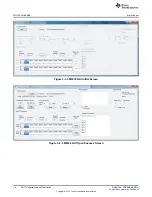
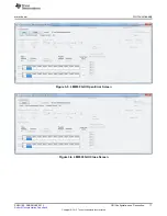
Page 16: ...w ti com Figure 3 3 LM8330 GUI Initial Screen Figure 3 4 LM8330 GUI Open Success Screen 16 GUI Configuration and Description SNVU166 FEBRUARY 2013 Submit Documentation Feedback Copyright 2013 Texas Instruments Incorporated ...

Page 17: ...ctionality Figure 3 5 LM8330 GUI Open Error Screen Figure 3 6 LM8330 GUI Close Screen 17 SNVU166 FEBRUARY 2013 GUI Configuration and Description Submit Documentation Feedback Copyright 2013 Texas Instruments Incorporated ...

Page 18: ...ters When the specific register is selected via the register dialog box the Register Address Attributes and Register Description fields are updated with the specific register information The multi byte write access will begin at the address indicated in the Register Address field with the number of data bytes entered in the Write Data grid beginning with Byte 0 Note the maximum number of bytes wri...

Page 19: ...in the Key to Test box in the Keypad Test section The keypad test begins with the 1 key and advances through all ten columns and all five rows of the keypad refer to Figure 3 8 The Status Pass Count and Fail Count fields are updated as the test progresses Note all 49 keys must be pressed released to complete the keypad test refer to Figure 3 9 and Figure 3 10 Figure 3 8 LM8330 GUI Keypad Test Figu...

Page 20: ...nctionality www ti com Figure 3 10 LM8330 GUI Keypad Test Failed Example 20 GUI Configuration and Description SNVU166 FEBRUARY 2013 Submit Documentation Feedback Copyright 2013 Texas Instruments Incorporated ...
Page 21: ...m Texas Instruments LM8330 I2 C Compatible Keypad Controller with GPIO PWM and IEC61000 ESD Protection data sheet 21 SNVU166 FEBRUARY 2013 Related Documentation from Texas Instruments Submit Documentation Feedback Copyright 2013 Texas Instruments Incorporated ...
Page 22: ...ency energy and has not been tested for compliance with the limits of computing devices pursuant to part 15 of FCC or ICES 003 rules which are designed to provide reasonable protection against radio frequency interference Operation of the equipment may cause interference with radio communications in which case the user at his own expense will be required to take whatever measures may be required t...

Page 23: ... its gain should be so chosen that the equivalent isotropically radiated power e i r p is not more than that necessary for successful communication This radio transmitter has been approved by Industry Canada to operate with the antenna types listed in the user guide with the maximum permissible gain and required antenna impedance for each antenna type indicated Antenna types not included in this l...

Page 24: ...er you obtained the Technical Regulations Conformity Certification as provided in Radio Law of Japan with respect to this product Also please do not transfer this product unless you give the same notice above to the transferee Please note that if you could not follow the instructions above you will be subject to penalties of Radio Law of Japan Texas Instruments Japan Limited address 24 1 Nishi Shi...

Page 25: ... property damage personal injury or death If there are questions concerning these ratings please contact a TI field representative prior to connecting interface electronics including input power and intended loads Any loads applied outside of the specified output range may result in unintended and or inaccurate operation and or possible permanent damage to the EVM and or interface electronics Plea...

Page 26: ...esponsible for compliance with all legal regulatory and safety related requirements concerning its products and any use of TI components in its applications notwithstanding any applications related information or support that may be provided by TI Buyer represents and agrees that it has all the necessary expertise to create and implement safeguards which anticipate dangerous consequences of failur...

Reviews: