GUI Functionality
3.2.2 Initialization and LED Control
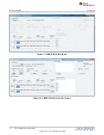
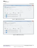
The initialization and LED control provides LM8330 initialization, LM8330 reset and control of the LED
mounted on the EVM. The initialization checkbox needs to be checked to configure the LM8330 for 8x10
keypad scanning. The LED control is provided to verify USB communication to the EVM.
Figure 3-7. LM8330 Initialization Example
3.2.3 I2C Byte Access
The I
2
C Byte Access section provides single byte read and write access to any slave address. The data
field is used for both read and write operation. Note: the Slave Addr, Offset and Data fields are
independent from the corresponding fields in the LM8330 registers section.
3.2.4 LM8330 Registers
The LM8330 registers section provides multi-byte read and write access to the LM8330 registers. The
LM8330 registers are organized by function as follows:
1. Keyscan: provides access to the Keyscan specific registers
2. PWM: provides access to the PWM specific registers
3. System: provides access to the System registers
4. GPIO: provides access to the GPIO specific registers
When the specific register is selected via the register dialog box the Register Address, Attributes, and
Register Description fields are updated with the specific register information. The multi-byte write access
will begin at the address indicated in the Register Address field with the number of data bytes entered in
the Write Data grid beginning with Byte 0 (Note: the maximum number of bytes written is limited to 10)
when the Write button is clicked. The multi-byte read access will begin at the address indicated in the
Register Address field for the number of bytes entered in the Read Byte Count box (Note: the maximum
number of bytes read is limited to 10) when the Read button is clicked.
3.2.5 Keypad Status
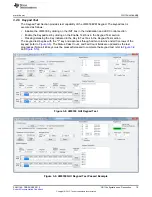
The Keypad Status section provides direct reporting of the Key Code, Key Value, and Key State. This
information is automatically updated by responding to the LM8330 interrupt (IRQN). If desired the interrupt
response can be disabled by unchecking the Auto Response checkbox. When operating in this mode the
user will need to manually read the EVTCODE register to ensure that no Key Codes are lost by overflow
of the EVTCODE buffer.
18
GUI Configuration and Description
SNVU166 – FEBRUARY 2013
Copyright © 2013, Texas Instruments Incorporated


