Hardware
10
SWRU518D – May 2017 – Revised May 2020
Copyright © 2017–2020, Texas Instruments Incorporated
IWR1443BOOST Evaluation Module mmWave Sensing Solution
Table 3. HD Connector Pin Definition (continued)
Pin Number
Description
Pin Number
Description
45
NC
46
AR_LVDSSCSI_CLKM
47
NC
48
GND
49
NC
50
AR_LVDSSCSI_1P
51
AR_SDA
52
AR_LVDSSCSI_1M
53
AR_SCL
54
GND
55
AR_RS232RX
56
AR_LVDSSCSI_0P
57
AR_RS232TX
58
AR_LVDSSCSI_0M
59
AR_NRST_MCU
60
GND
PGOOD – This signal indicates that the state of the onboard VIO supply for the IWR device coming from
the onboard PMIC. A high on the PGOOD signal (3.3 V) indicates the supply is stable. Because the I/Os
are not failsafe, the MCU must ensure that it does not drive any I/O signals to the IWR device before this
I/O supply is stable, to avoid leakage current into the I/Os.
2.4.3
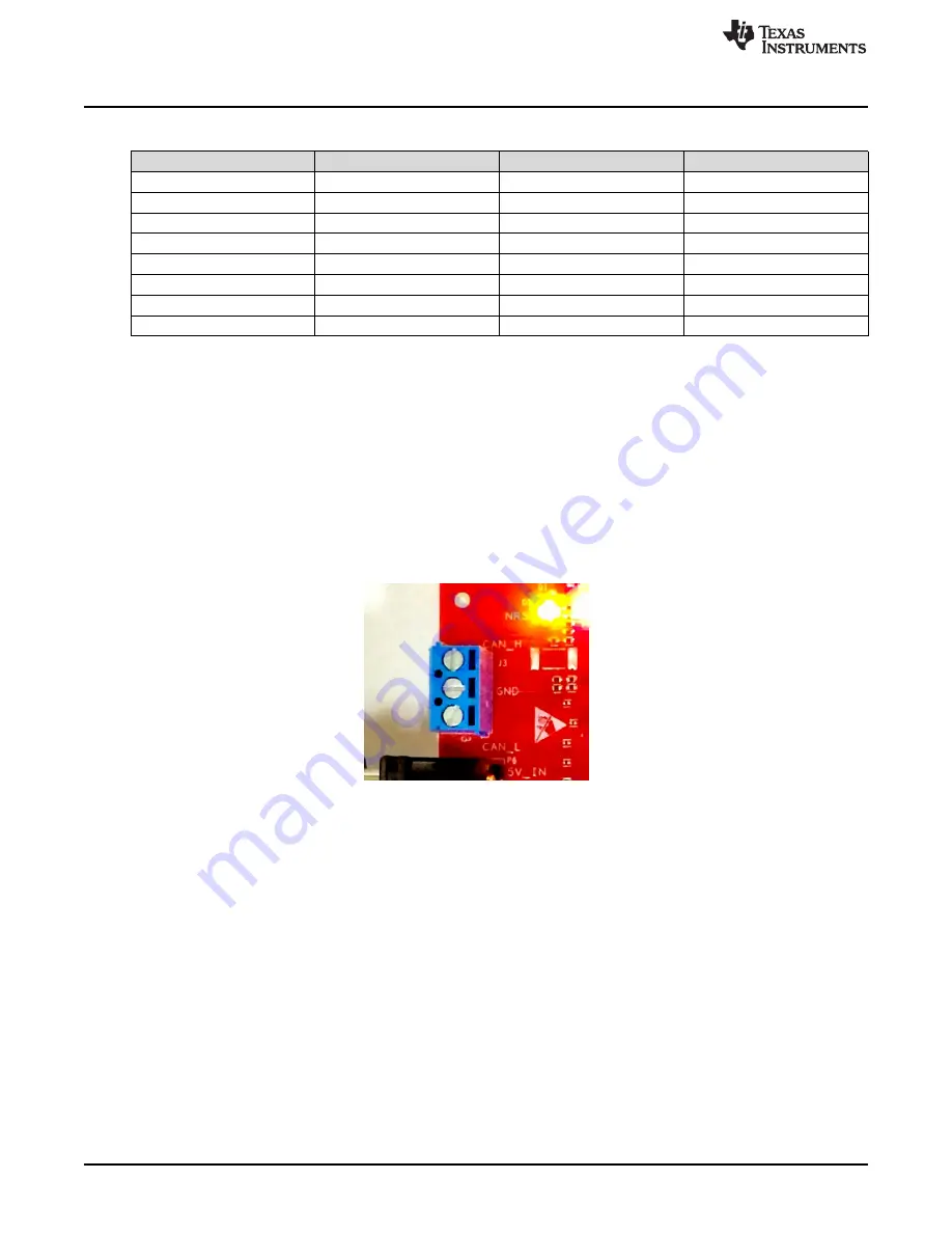
CAN Interface Connector
The J3 connector provides the CAN_L and CAN_H signals (see
) from the onboard CAN
transceiver (SN65HVDA540). These signals can be directly wired to the CAN bus.
Because the digital CAN signals (TX and RX) are muxed with the SPI signals on the IWR device, one of
the two paths must be selected. To enable the CAN interface, the R11 and R12 resisters muct be
populated with 0
Ω
, and the R4, R6, R28, and R63 resisters must be removed to disconnect the SPI path.
Figure 8. CAN Connector


