background image

www.ti.com

Hardware Description and Setup

3

SNLU222B – December 2016 – Revised September 2019

Submit Documentation Feedback

Copyright © 2016–2019, Texas Instruments Incorporated

FPC401 and FPC402 Evaluation Module (EVM) User’s Guide

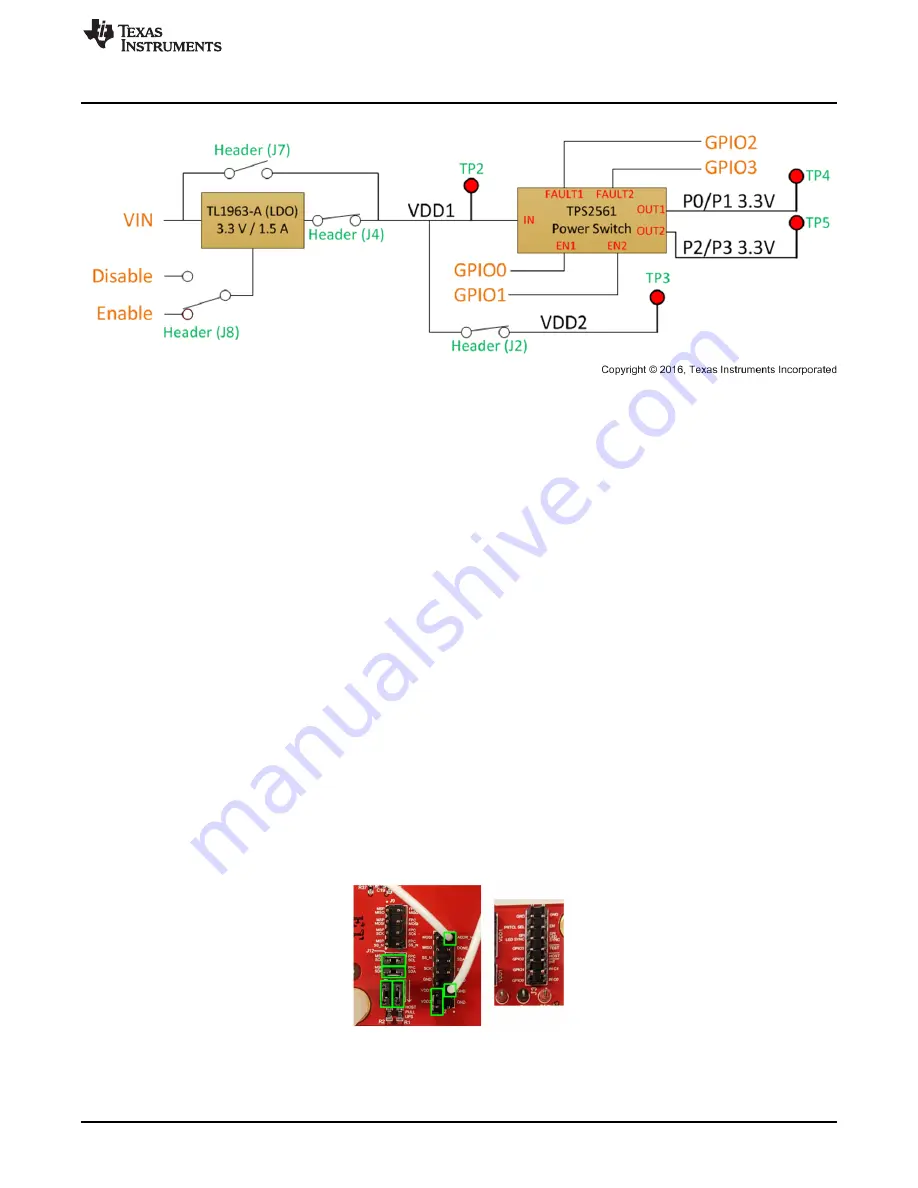
Figure 2. Power Block Diagram – Configured for LDO Use

1.2

Communication Protocol Configuration

The following sections describe how to configure the FPC401EVM and FPC402EVM for I2C and SPI
protocols.

1.2.1

I2C Configuration

For I2C communication with the onboard MSP430, refer to

Figure 3

and configure the board based on the

following procedure.

1. Leave the PRTCL_SEL pin disconnected (header J3).

2. Connect the MSP430 SCL and SDA to the FPC SCL and SDA through header J12. The SPI header

(J9) should be disconnected.

3. Connect the 2.7-k

Ω

pullup resistors through header J1.

4. Connect the VDD2 pin to the VDD1 pin through header J2.

5. Connect the ADDR_N pin to GND through header J2 with the provided jumper wire.

For I2C communication with an external host controller, disconnect the MSP430 SDA and SCL. Connect
the FPC SDA and SCL pins to the SDA and SCL pins of the host controller. Only connect the onboard
pullup resistors if the host board does not have pullups.

To control multiple EVMs, connect all the SDA and SCL pins together. Only one board should have the
MSP430 and pullup resistors connected to these pins. The ADDR_N of the first device should be tied to
GND as shown in

Figure 3

. Connect DONE_N pin of the first device to the ADDR_N of the second

device, and the DONE_N pin of that device to the following device in a daisy-chained fashion until all
ADDR_N pins are connected. Connect the final DONE_N pin to GND. See the data sheet for more details
on how I2C is configured.

Figure 3. I2C Configuration

Summary of Contents for FPC401

Page 1: ...ive property of Texas Instruments No disclosure of information or drawings shall be made to any other person or organization without the prior consent of Texas Instruments Contents 1 Hardware Description and Setup 2 1 1 Power Configuration 2 1 2 Communication Protocol Configuration 3 2 FPC401 EVM GUI Description and Setup 5 2 1 Installation 6 2 2 Initializing Communication 6 2 3 Local FPC Read and...

Page 2: ...d J13 are disconnected 3 If USB power is used to power the FPC ensure the LDO and VIN and disconnected from VDD1 disconnect headers J4 and J7 Connect the 3 3 V of the MSP430 microcontroller to VDD1 through header J13 Note that a typical computer USB port is only able to supply up to 100 mA which will be enough to power the FPC and passive modules that is DAC but it will not be enough to power acti...

Page 3: ... resistors through header J1 4 Connect the VDD2 pin to the VDD1 pin through header J2 5 Connect the ADDR_N pin to GND through header J2 with the provided jumper wire For I2C communication with an external host controller disconnect the MSP430 SDA and SCL Connect the FPC SDA and SCL pins to the SDA and SCL pins of the host controller Only connect the onboard pullup resistors if the host board does ...

Page 4: ...der J12 should be disconnected 3 Connect the VDD2 pin to the VDD1 pin through header J2 For SPI communication with an external host controller disconnect the MSP430 MOSI MISO SCK and SS_N pins Connect the FPC MOSI MISO SCK and SS_N pins to the MOSI MISO SCK and SS_N pins of the host controller To control multiple EVMs with SPI connect all the SCK and SS_N pins to a single MSP430 SCK and SS_N pins ...

Page 5: ...ack Copyright 2016 2019 Texas Instruments Incorporated FPC401 and FPC402 Evaluation Module EVM User s Guide 2 FPC401 EVM GUI Description and Setup The FPC401 EVM GUI is used to program both FPC401EVM and FPC402EVM The general procedure for setting up the FPC401 GUI is described in the sections below Figure 5 FPC401 EVM GUI ...

Page 6: ...and the protocol I2C or SPI highlighted by Figure 6 Click OPEN LINK to establish communication with the MSP430 through USB and initialize the device In I2C mode this will configure the MSP430 and automatically configure the I2C addresses of all connected FPC401s so that each one has a unique address In SPI mode this will configure the MSP430 and establish the length of the SPI message Each time th...

Page 7: ...ich FPC is being controlled starting at instance 0 The Port selects which port is being configured where 0 is the port 0 of FPC instance 0 and 4 is port 0 of FPC instance 1 The Broadcast switch will broadcast commands to all FPCs if set to 1 Note that if a command that targets a port is broadcasted not all ports will be modified Instead only ports that match the local port of the selected instance...

Page 8: ... tab Select the instance number and register offset address to be read or written to To write select a value using the radio boxes in the WRITE COMMAND section or type the desired hex value and click EXECUTE WRITE To read click EXECUTE READ The RESET FPC REGISTERS button will reset the instance s local FPC registers Note that performing a register reset in I2C mode will restore the default I2C add...

Page 9: ...a remote access read or write on a downstream port select the Downstream Reads and Writes tab Select the port number downstream device I2C address and register offset address To write select a value using the radio boxes in the WRITE COMMAND section or type the desired hex value and click EXECUTE WRITE To read click EXECUTE READ The Set I2C Rate switch will toggle the I2C rate of the downstream be...

Page 10: ...and Configuration tab The Enable Periodic Update button will update the indicator of each input GPIO and output periodically set by the Update Period ms slider This will also update the Port s Aggregated Interrupt Flag which determines if any interrupt of the selected port has been triggered To modify the state of the GPIOs modify the GPIO 0 1 2 3 Set drop down menus and click SET GPIOS To modify ...

Page 11: ... port input trigger source and trigger edge Click SET to configure To check and clear the status of all of the interrupts of the selected port click UPDATE AND CLEAR Some of these interrupts are configured in other sections To enable the SDA and SCL instances stuck at 0 interrupts click SDA STUCK ENABLE and SCL STUCK ENABLE buttons These buttons enables the interrupts for all ports of the selected...

Page 12: ...r and click SET in the PWM MODE SETTINGS section Since the PWM duty cycle is 0 by default the LEDs will not be visible until this is modified In BLINK mode configure the On Time and Off Time and click SET under the BLINK MODE SETTINGS section To synchronize the LEDs click the SYNCHRONIZE LEDS button at the bottom of the page This will automatically forward the LED clock for synchronization across ...

Page 13: ...ister offset address In the PERIODIC PREFETCH SETTINGS section enter the prefetch period in milliseconds and click START PREFETCH A period of 0 ms is a one time prefetch To stop the periodic prefetch click the STOP PREFETCH button This will not clear the gate bit so any downstream read in the prefetched range will read from the FPC memory To reset the gate bit and force the FPC to read from the do...

Page 14: ...en Interrupt Settings tab The FPC is able to monitor up to four bytes per port and the monitored byte index is controlled by the Byte Number input Select the port number register address to be monitored and the bits to be monitored and click SET Note that the monitored register address must be within the prefetched range for the selected port Click CHECK CLEAR DATA to determine which bits of the f...

Page 15: ...e downstream ports select the Scheduled Write tab Select the port number device address register offset address and write value and click EXECUTE SCHEDULED WRITE This will issue a write to the selected port and may be broadcasted to write to multiple ports across multiple FPC instances The CONFIGURE COMMON SCHEDULED WRITE section works similarly but the user may also select which of the ports to b...

Page 16: ...mit Documentation Feedback Copyright 2016 2019 Texas Instruments Incorporated Revision History Revision History NOTE Page numbers for previous revisions may differ from page numbers in the current version Changes from Original November 2016 to B Revision Page First public release 2 ...

Page 17: ...ry 17 SNLU222B December 2016 Revised September 2019 Submit Documentation Feedback Copyright 2016 2019 Texas Instruments Incorporated Revision History Changes from Original November 2016 to B Revision Page First public release 2 ...

Page 18: ...other than TI b the nonconformity resulted from User s design specifications or instructions for such EVMs or improper system design or c User has not paid on time Testing and other quality control techniques are used to the extent TI deems necessary TI does not test all parameters of each EVM User s claims against TI under this Section 2 are void if User fails to notify TI of any apparent defects...

Page 19: ... These limits are designed to provide reasonable protection against harmful interference in a residential installation This equipment generates uses and can radiate radio frequency energy and if not installed and used in accordance with the instructions may cause harmful interference to radio communications However there is no guarantee that interference will not occur in a particular installation...

Page 20: ...y for convenience and should be verified by User 1 Use EVMs in a shielded room or any other test facility as defined in the notification 173 issued by Ministry of Internal Affairs and Communications on March 28 2006 based on Sub section 1 1 of Article 6 of the Ministry s Rule for Enforcement of Radio Law of Japan 2 Use EVMs only after User obtains the license of Test Radio Station as provided in R...

Page 21: ... any interfaces electronic and or mechanical between the EVM and any human body are designed with suitable isolation and means to safely limit accessible leakage currents to minimize the risk of electrical shock hazard User assumes all responsibility and liability for any improper or unsafe handling or use of the EVM by User or its employees affiliates contractors or designees 4 4 User assumes all...

Page 22: ...OR DAMAGES ARE CLAIMED THE EXISTENCE OF MORE THAN ONE CLAIM SHALL NOT ENLARGE OR EXTEND THIS LIMIT 9 Return Policy Except as otherwise provided TI does not offer any refunds returns or exchanges Furthermore no return of EVM s will be accepted if the package has been opened and no return of the EVM s will be accepted if they are damaged or otherwise not in a resalable condition If User feels it has...

Page 23: ...se resources are subject to change without notice TI grants you permission to use these resources only for development of an application that uses the TI products described in the resource Other reproduction and display of these resources is prohibited No license is granted to any other TI intellectual property right or to any third party intellectual property right TI disclaims responsibility for...

Reviews: