background image

START

COMPUTER

TROUBLE

INDICATION

?

DEAD

COMPUTER

SYMTOMS

?

RUN

SELF TEST

ERROR

MESSAGE

?

MODEM

PROBLEM

?

RUN

DIAGNOSTICS

DIAGNOSTICS

ERROR MSG

?

NO

YES

NO

YES

SEE PARAGRAPH

5.3.5

NO

YES

SEE PARAGRAPH

5.3.4

NO

SEE

PARAGRAPHS

5.3.1 & 5.3.2

NO

WHEN POWER SWITCH

SET TO ON,, NO

INDICATION OF POWER;

SCREEN DARK, STATUS

LED's EXTINGUISHED

SET POWER SWITCH

TO ON. SELFTEST

AUTOMATICALLY RUNS

YES

See Appendix D
(PC Doctor)

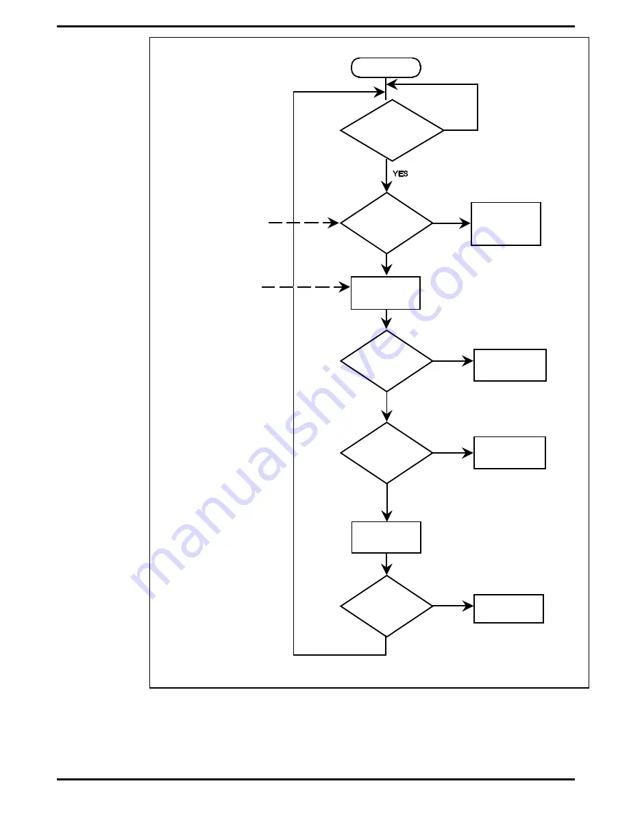
Figure 5-1  Troubleshooting Flowchart


5-2 

Troubleshooting

Summary of Contents for Extensa 450 Series

Page 1: ...Maintenance Manual Extensatm 450 Series Notebook Computers 9805725 0001 November 1995 ...

Page 2: ...r application The manager must rely on judgement of what is best for his or her business Address all correspondence regarding orders to Texas Instruments Incorporated P O Box 6102 M S 3255 Temple Texas 76503 Extensa 450 TravelMate 5000 4000M 4000E 4000 and BatteryPro are trade marks of Texas Instruments Incorporated The icons in the Windows Notebook and Startup groups are copyrighted by Texas Inst...

Page 3: ...9 1 5 Standard Test Features 1 10 1 6 Notebook Assemblies and Subassemblies 1 10 1 6 1 Cover Display Assembly 1 11 1 6 2 System Base Assembly 1 11 1 7 Extensa 450 Series Notebook Specifications 1 12 1 8 Agency Approvals 1 13 Section 2 Installation 2 1 Introduction 2 1 2 2 Unpacking Instructions 2 1 2 3 Installing Notebook Options 2 1 2 3 1 Installing Dual Inline Memory Module s 2 1 2 3 2 Installin...

Page 4: ...cators 3 1 3 2 1 LCD Brightness Control 3 2 3 2 2 Button Switches 3 2 3 2 3 Cover Release Latch 3 3 3 2 4 Touch Pad Controls 3 3 3 2 5 Keyboard Mode LEDs 3 3 3 3 Operating Procedures 3 3 3 3 1 Floppy Drive Operating Procedures 3 4 3 3 2 Installing Removing PCMCIA Options 3 4 3 3 3 Computer Hot Keys 3 5 3 3 4 Responding to Low Battery Conditions 3 5 3 3 5 Minimizing Power Usage 3 5 3 3 6 Recharging...

Page 5: ...Cleaning the Computer 6 1 6 2 2 Protecting the Disk Drives 6 2 6 2 3 Handling the Computer Battery Pack 6 2 6 2 4 Restoring System Software 6 2 6 3 Required Tools and Equipment 6 3 6 4 Notebook Field Replaceable Parts and Assemblies 6 3 6 4 1 Cover Display Assembly 6 3 6 4 2 System Base Assembly 6 4 6 5 FRU Removal and Replacement Procedures 6 6 6 5 1 Removing Replacing the Notebook Battery Pack 6...

Page 6: ... 5 16 Removing Replacing the Main Board 6 16 6 5 17 Removing Replacing the Secondary Battery Board 6 18 Appendix A Self Test Error Messages A 1 Introduction A 1 Appendix B Connector Pinouts B 1 Introduction B 1 Appendix C PC Doctor Diagnostics C 1 Introduction C 1 C 2 Starting PC Doctor C 1 C 3 Keyboard Navigation C 2 C 4 Mouse Navigation C 2 C 5 PC Doctor Menus C 3 C 5 1 Online Help C 3 C 5 2 Dia...

Page 7: ...puter in a desktop environment Section 3 Operating Instructions Describes the notebook operating controls and indicators and modes of operation Section 4 Theory of Operation Describes detailed theory of operation for Extensa series notebooks Section 5 Troubleshooting Provides troubleshooting procedures for the Extensa 450 series notebooks Section 6 Field Service Provides corrective maintenance pro...

Page 8: ...ensa 450 series software including the TI custom utilities Windows 95 Help online PC Doctor Help and Technical Reference online Ordering Parts and Supplies To order a copy of any TI publication or to order option kits spare parts or supplies for your system contact your TI Reseller or Telephone Toll free 1 800 TI TEXAS viii Preface ...

Page 9: ... level servicing information for the Texas Instruments Extensa tm 450 Series of Notebook Computers Figure 1 1 This section provides a general overview and specifications for the Extensa 450 Series Notebook Computers Figure1 1 Extensa 450 Series Notebook Computer General Description 1 1 ...

Page 10: ...dows 95 Plus Microsoft Works Quicken SE Lotus Organizer and Microsoft Entertainment Pack Windows 95 Plus Microsoft Works Quicken SE Lotus Organizer and Microsoft Entertainment Pack 1 3 International Product Versions The Extensa 450 Series Notebooks are available in one of 15 domestic and international configurations as listed in Table 1 2 Table 1 2 Notebook Domestic International Configurations Co...

Page 11: ...st 2 7 mm travel built in touchpad pointing device Most standard external device interfaces including serial parallel PS 2 external VGA and serial infrared wireless port Removable 3 5 1 44 MB Floppy Drive second Lithium Ion battery or a type III PCMCIA device can be installed in its place with option Choice of LCD displays 10 4 Dual Scan Color or 9 4 Active Matrix Color LCD AC Adapter with autosen...

Page 12: ...Figure 1 2 Extensa 450 Series Features 1 4 General Description ...

Page 13: ...puter 9 Pin Serial Port for attaching any RS 232 type serial device to the Notebook 15 Pin External VGA Monitor Port for attaching an external monitor 6 Pin PS 2 Port to attach an external Keyboard or Mouse Second 6 Pin PS 2 Port for attaching an external Keyboard Mouse AC Adapter Connector for attaching the AC Adapter to the notebook Figure 1 3 Notebook External Ports General Description 1 5 ...

Page 14: ...hanced type keyboard with the standard character and function keys plus 12 programmable function keys F1 through F12 Using the Special Function Fn key which assigns multiple functions to keys the keyboard can emulate the IBM 101 102 keyboards using 83 keys 84 on international models The keyboard has a 2 77 mm stroke and features a special keyboard interface chip that can detect multiple levels of ...

Page 15: ...nsa Series Notebook Computers contain a set of three buttons switches and five LED displays just above the keyboard including Power Setup and Standby Suspend Buttons Switches Caps Lock indicator This LED indicates that the keyboard is locked in the uppercase mode To switch to the lowercase mode press the Caps Lock key Num Lock indicator This LED lights when you press the NumLk key to toggle on the...

Page 16: ...hts when Notebook is in Standby mode 1 4 4 Standard Power Features Notebook power for the Extensa 450 Series Notebook Computers is provided by an AC Adapter and a rechargeable 10 8 V 2400 mAh Duracell nickel metal hydride NiMH battery pack that installs in a power bay near the front of the notebook right side A second lithium ion battery may optionally be installed in the Floppy Drive bay when the...

Page 17: ...ome standard with the following application packages installed Microsoft Works Quicken SE Lotus Organizer Microsoft Entertainment Pack No 4 1 4 7 Notebook Expansion Capabilities Expansion capabilities built into the Extensa notebook series include User installable expansion RAM memory to a maximum of 32 MB By removing the floppy drive you can add either a second battery pack or a Type III PCMCIA d...

Page 18: ...ite of diagnostic tests are available to further test selected parts of the system 1 6 Notebook Assemblies and Subassemblies The Extensa Series Notebooks are modular in design and can be disassembled for maintenance purposes using a standard set of flat bladed Phillips head and hexagonal screwdrivers The major assemblies that comprise a typical notebook in the Extensa family are shown in Figure 1 ...

Page 19: ...ing screws on the bottom of the computer 1 6 2 System Base Assembly As shown in Figure 1 7 the majority of the notebook s field replaceable units FRUs are located in the system base assembly These FRUs include Main Board Assembly Hard Disk Drive Assembly Memory Board Assembly Up to two Dual Inline Memory Modules Serial Infra red Board Assembly Floppy Drive Assembly Secondary Battery Board Assembly...

Page 20: ...B Video Bus VLBUS with Graphics Accelerator VLBUS with Graphics Accelerator Keyboard Pointing Device Ergonomic Keyboard Yes Yes Built In Touchpad Yes Yes Storage Floppy Drive 3 5 1 44MB 3 5 1 44MB Hard Drive 340 Million Byte 340 Million Byte Interfaces Serial RS232 Port Yes Port Adapter Yes Port Adapter Parallel Port EPP ECP Yes Yes External VGA Port Yes Port Adapter Yes Port Adapter External PS2 ...

Page 21: ...L X 1 7 H X 8 2 W Wight specifications do not include Floppy Drive AC Adapter or 2nd Battery 1 8 Agency Approvals All Extensa 450 Series products meet the following standards Underwriter s Lab UL Standard 1950 safety Canadian Standards Association CSA Standard 220 safety FCC CFR 47 Part 15 Subpart J FCC Level B EMI Canadian Department of Communications DOC Certification VDE 0871 Class B EMI Genera...

Page 22: ... accessory box remove the contents n Note Save the shipping containers and packaging for later reuse 2 3 Installing Notebook Options If you have no options to install at this time skip to Paragraph 2 3 Otherwise continue with Paragraph 2 2 1 2 3 1 Installing Dual Inline Memory Module s n Note If not installing RAM Expansion option at this time skip to the next para graph c Caution The Dual Inline ...

Page 23: ...he keyboard as a hinge lift the front edge of the keyboard up and lay it against the display 6 Remove the two Phillips head screws holding heatsink to the Main Board and remove the heatsink by lifting it upwards and out of the unit 7 Insert the edge of the DIMM Board into the rear of either available connector see Figure 2 1 Use a rocking motion to fully insert the module Push downwards on each si...

Page 24: ... 3 To insert a PCMCIA card align the card with the socket and slide the card into the socket until it locks into place To install a Type III option you must remove the Floppy Drive from the right side of the notebookand install the PCMCIA Option Assembly 4 To eject a PCMCIA card first ensure that the notebook is not accessing the memory card or device Under Windows 95 go to the Control Panel PC Ca...

Page 25: ...to Figure 2 3 and use the following procedure 1 Remove the port adapter and any accessories from its shipping carton 2 Disconnect the AC Adapter from the notebook if attached 3 Open the rear connector door on the notebook and attach the Port Adapter to the notebook as shown in Figure 2 3 Figure 2 3 Installing the Port Adapter 2 4 Installation ...

Page 26: ... second Lithium Ion battery pack To remove or replace the battery pack follow the steps below 1 Power off the notebook being sure to save your data first 2 Locate the battery door right side of notebook near the front Press the battery door inwards and slide the door toward the front of the notebook remove the battery door 3 Insert a new or recharged battery pack into the battery compartment bay M...

Page 27: ...s connect to the Notebook via the connectors on the rear of the notebook and on the rear of the Port Adapter supplied with the notebook see Figure 2 5 for port assignments 2 5 1 Installing an External Keyboard Mouse As shown in Figure 2 6 the notebook has provisions for two external PS 2 compatible devices keyboard mouse etc that may be attached to the notebook The pinouts for the 6 pin Mini DIN c...

Page 28: ...off 2 Locate the external PS 2 ports at the rear of the notebook see Figure 2 6 3 Attach the PS 2 cable from your mouse and or keyboard cable to the PS 2 port s 4 Power on any other peripheral devices you may have connected to the notebook and then power up the notebook PS 2 Ports Figure 2 6 PS 2 Port Assignments Pinouts Installation 2 7 ...

Page 29: ...ur notebook Refer to the manual which accompanied your printer for instructions on configuring your operating environment 2 5 3 Installing External Serial Port Device The notebook contains an RS 232 serial port with a male DB 9 connector as shown in Figure 2 8 The serial ports are used to interconnect such devices as External Modem Serial Printer Any device that uses an RS 232 interface To connect...

Page 30: ...ce to a parallel port or video port this may cause damage to the Note book and or peripheral device If you are uncertain of what type connector the external device has refer to the technical manual for the external device Figure 2 8 Serial Port Location Pinouts Installation 2 9 ...

Page 31: ...appropriate end of the monitor cable to the VGA port on your notebook If the monitor cable connectors have retaining screws tighten them down 4 If necessary connect the monitor power cable to the monitor and plug the monitor power cable into an electrical outlet 5 Power on the monitor as well as any other peripheral devices connected to the notebook then power up the notebook 2 5 5 Installing SIR ...

Page 32: ...ers can damage the unit 1 Remove the AC adapter from the packaging Connect the round coaxial connector supplied with the notebook to the power receptacle on the rear of the notebook as shown in Figure 2 10 2 Connect the female side of the AC Power cord to the AC Adapter and connect the male end to a grounded AC outlet Figure 2 9 External Monitor Port Pinouts Installation 2 11 ...

Page 33: ...t the computer automatically loads its operating system and Windows environment If self test fails to complete and an error message is displayed try powering down the computer for a couple of minutes and turning power back on to repeat self test If the error message persists see Section 6 for troubleshooting information 2 8 Configuring the System The first time you power up the notebook it automat...

Page 34: ...em software using the Backup Utility under Windows 95 In the event of a disk problem you can restore your system using the Restore Utility and the set of backup diskettes you ve just created 2 10 Loading Application Software For assistance in loading Application Software refer to Chapter 5 in the Extensa Series Notebook Computer User s Reference Manual Installation 2 13 ...

Page 35: ...01 3 2 Notebook Controls and Indicators The Extensa Series Notebooks are equipped with the following controls and indicators Group of five LEDs just above the keyboard Sleep Mode Hard Drive Activity Num Lock Caps Lock and Scroll Lock Power Setup and Standby Suspend buttons adjacent to the status LEDs Single Power LED on the leftrear corner of the notebook Touch Pad and two select buttons at base o...

Page 36: ... power to the unit Pressing the Power button causes power to be applied to the notebook and power up self test to be run The PWR LED left rear corner of notebook glows green and the computer then loads Windows 95 When the Power button is pressed again the Notebook powers down and all data in RAM memory is lost Standby Suspend Button Switch an alternate action touch switch that invokes the save to ...

Page 37: ...ock Indicator this LED indicates that the keyboard is locked in the Uppercase mode To switch to the Lowercase mode press the Caps Lock key on the keyboard NUM Num Lock Indicator This LED lights when you press the Fn F7 NumLk keys to toggle on the numeric keypad lock function When the LED is On the embedded numeric keyboard keys generate AT keypad characters and functions when pressed in conjunctio...

Page 38: ...mage or loss 3 3 2 Installing Removing PCMCIA Options PCMCIA cards are inserted and ejected in much the same way as diskettes Type I or Type II PCMCIA options may be installed in the compartment on the left side of the notebook Type III Options may be installed on the right side of the notebook with the Floppy Drive removed and the PCMCIA Option installed To insert a PCMCIA card align the card wit...

Page 39: ... pack Press CTRL STANDBY to shut off the alarm if its enabled Save RAM Disk if using RAM Disk feature Press Standby Suspend button to put the computer in Standby suspend mode whenever you are not actively using the computer This will save all your work and remember the application and file you were previously using when you return to the On condition Power down the system if you do not need the co...

Page 40: ...ure The following items are required to rebuild the system software Set of backup diskettes of the system software Operational Notebook Insert the Windows 95 Startup Diskette in the Notebook s floppy drive and power up the system n Note For additional operating procedures refer to to the Extensa 450 Series Note book Computer User s Manual Texas Instruments Part No 9803942 0001 3 6 Operating Instru...

Page 41: ...X4 Processor The processor operates in conjunction with RAM and ROM Memory on the Memory Board and other control logic on the Main Board to process software instructions BIOS Windows 95 and Applications Primary control for the Processor Memory subsystem is implemented with the M1429L PC AT Chipset Address buffering and real time clock function is implemented with an M1441L The memory subsystem imp...

Page 42: ...Figure 4 1 Notebook Functional Block Diagram 4 2 Theory ...

Page 43: ...080 08F DMA Page Register 0A0 0A1 Interrupt Controller 2 0C0 0DF DMA Controller 2 1F0 1F7 Hard Disk Select 178 17A 6377 Registers 1F0 1F7 Hard Disk Select 3F6 3F7 278 27F Parallel Port 3 35F 36F Special I O Ports 378 37A Parallel Port 2 3BC 3BE Parallel Port 1 3C0 3C5 3C6 3C9 Video DAC 3C0 3CF Enhanced Graphics Display 3D0 3DF Color Graphics Adapter 3E0 3E1 PCMCIA Controller 3F0 3F7 Floppy Disk Co...

Page 44: ...agement unit 2 NMI Parity Error Detected I O Channel Error 3 IRQ0 Interval Timer Counter 0 Output 4 IRQ1 Keyboard IRQ 2 Interrupt from controller 2 cascade 5 IRQ8 Real Time Clock 6 IRQ 9 Cascaded to INT 0AH IRQ 2 7 IRQ10 Reserved 8 IRQ 11 Reserved 9 IRQ 12 PS 2 Mouse 10 IRQ13 INT from Coprocessor 11 IRQ14 Hard Disk Controller 12 IRQ15 Reserved 13 IRQ3 Serial Comm Port 2 14 IRQ4 Serial Comm Port 1 ...

Page 45: ...ible with the DP8473 the 765A and N82077 16 byte FIFO default disabled Burst and Non burst modes Perpendicular Recording drive support New high performance internal digital data separator no external filter components required Low power CMOS with enhanced power down mode Automatic media sense support Two UARTS Software compatible with the PC16550A and PC16450 MIDI compatible Infrared support on UA...

Page 46: ...m is implemented with a Cirrus Logic 6245 high performance flat panel RT VGA controller and supporting logic and video RAM 512KB The major features of the VGA controller include Highly integrated design flat panel CRT VGA controller RAMDAC clock synthesizer Multiple Bus Architecture Integrated Interface Local Bus 32 bit CPU Direct and VL EISA ISA PC AT 16 bit Bus Advanced frame buffer architecture...

Page 47: ...ting the disk drive erases any data that may be stored on the disk Therefore do not attempt a format of the hard disk unless the computer self test and diagnostics confirm that the disk has not been formatted A Hard Drive activity LED is located along the front edge of the notebook This LED lights during hard driver read write accesses c Caution The notebook should not be moved when the HDD LED is...

Page 48: ...ng support Easy host interface using ISA I O addresses 03E0h 03E1h Mixed voltage 3 3V or 5V operation Dual socket interface 208 pin QFP 4 2 7 Power Subsystem The Power Subsystem consists of the following major parts Power Management hardware and software components AC Adapter Primary Battery Board Primary Battery Pack Secondary Battery Board Secondary Battery Pack 4 2 7 1 Power Management The note...

Page 49: ...removed 4 2 7 3 Primary Battery Pack The Extensa Series Notebooks use the Duracell DR35 as the primary battery pack Specifications for the Primary Battery Pack are provided in Table 4 4 Table 4 4 Primary Battery Pack Specifications Function Specifications Battery type NiMH Nickel Metal Hydride Cell structure 9 cells per pack in series Nominal voltage 10 8 V Cell energy capacity Typical Minimum 240...

Page 50: ...tery Pack As an optional feature the Floppy Drive can be removed from the notebook and a Li Ion Lithium Ion secondary battery pack can be installed in the same cavity to provide additional battery operating time 4 10 Theory ...

Page 51: ... of the following Notebook power system including battery packs and AC Adapter connections See Paragraph 5 4 Switch settings ensure Power switch is On and press Standby switch to ensure that Notebook is not in Standby mode press Shift to ensure the notebook is not in Auto Suspend mode All external cabling if any Check LCD Contrast adjustment Dual Scan version only Record and attempt to resolve any...

Page 52: ...RROR MSG NO YES NO YES SEE PARAGRAPH 5 3 5 NO YES SEE PARAGRAPH 5 3 4 NO SEE PARAGRAPHS 5 3 1 5 3 2 NO WHEN POWER SWITCH SET TO ON NO INDICATION OF POWER SCREEN DARK STATUS LED s EXTINGUISHED SET POWER SWITCH TO ON SELFTEST AUTOMATICALLY RUNS YES See Appendix D PC Doctor Figure 5 1 Troubleshooting Flowchart 5 2 Troubleshooting ...

Page 53: ...y problem you first solve this problem before running diagnostics If the computer powers up and displays messages on the LCD or emits a series of beeps skip to Paragraph 5 4 3 for further instructions 5 3 1 Troubleshooting a Power Supply Problem If the computer does not power up when the Power Switch is set to the ON position you most likely have a malfunction in the power subsystem loss of power ...

Page 54: ...e Power Supply Board and or Battery Board as described in Section 6 5 3 2 Troubleshooting a Display Problem If the LCD remains blank when you turn on the computer and the status indicators light check the following controls on the display See Figure 3 1 Figure5 2 Troubleshooting Block Diagram 5 4 Troubleshooting ...

Page 55: ... require you to use keystroke se quences such as Ctrl Alt Del To execute a keystroke sequence such as this you must press all three keys simultaneously 5 3 3 1 Self Test Error Messages Upon successful completion of the self test the computer automatically loads its operating system and other built in utilities If the self test fails to complete successfully the display shows one of the error messa...

Page 56: ...Functionally PC Doctor includes the following Group of nine non Interactive diagnostic tests that perform a non destructive test of the major hardware functions in the notebook Processor Memory System board video section serial and parallel ports when loopback adapters are installed hard disk and floppy disk Group of seven Interactive tests require operator input for testing the keyboard video sec...

Page 57: ... repeat function Video tests the LCD and external VGA character sets and colors Speaker tests the volume response at different frequencies Mouse tests the mouse driver buttons and functionality Joystick calibrates the external joystick connected to the system and tests the joystick buttons Diskette Drive checks diskette drive functionality Maximum System Load thoroughly exercises system to the max...

Page 58: ...sensitive help feature pressing F1 twice in a row calls up the online Technical Reference Manual for PC Doctor Scrolling windows which show the results of various operations use the following keys Page Up Page Down moves the screen one page at a time F2 Prints the log to PRN F3 saves the log to a file You can also use the mouse or Point to interact with PC Doctor The leftmost Select key is used to...

Page 59: ... LCD displays the diagnostics Header n Note There are a number of command line switches that can be entered when starting up PC Doctor to enable automatic virus scanning enable loopback testing of serial parallel ports work from the remote menu if per forming remote operations etc To get a listing of the available command line switches startup PC Doctor with the following command PCDR and press En...

Page 60: ...d the display screen 6 2 1 Cleaning the Computer When it is necessary to clean the plastic case and keyboard use a soft lint free cloth slightly dampened with a mild detergent solution or use the contents of any commercially available computer cleaning kit c Caution Never use alcohol petroleum based solvents or harsh deter gents to clean your computer Also never spray any liquids directly on the c...

Page 61: ...o direct sunlight moisture or chemical compounds Do not disassemble the battery pack Do not use the battery pack to power other devices Do not short the battery leads or connect the battery with reversed polarity Never attempt to charge the battery pack in any way other than as described in this manual Always charge the battery pack as soon as possible after a low battery indication 6 2 4 Restorin...

Page 62: ...ok Each of these two assemblies contain FRUs as described in the following subparagraphs 6 4 1 Cover Display Assembly As shown in Figure 6 1 the Cover Display Assembly contains the LCD screen Power Inverter Board and Converter Board The DSSTN models also include a Slide Pot Board not used with the TFT models The Field Replaceable Units FRUs within the Cover Display Assembly are provided in Table 6...

Page 63: ...9 4 6 5 9 Bezel TFT 9 4 455T 6 5 9 6 4 2 System Base Assembly As shown in Figure 6 2 the System Base Assembly houses a variety of field replaceable subassemblies and components The FRUs and paragraph references for removal replacement procedures are listed in Table 6 2 Table 6 3 contains a listing of Customer non technical user replaceable units CRUs and associated TI Part Numbers n Note FRU level...

Page 64: ...lder Assembly 6 5 4 Floppy Drive Assembly 6 5 3 Lower Case Assembly Ref Hard Disk Drive 340 Million Byte 12 5mm 6 5 4 Upper Case Assembly 6 5 10 Keyboard Assembly 6 5 5 Table 6 3 Notebook CRUs Customer Replaceable Units CRU Description TI Part No Reference Paragraph No Internal Battery Pack Ni MH 9803928 0001 6 5 1 Battery Pack Li ION Option 9803929 0001 6 5 3 4MB RAM Module 9803932 0001 6 5 7 8MB...

Page 65: ...dure for removing and replacing the battery pack s is as follows 1 Turn off the computer 2 Locate the battery door right side of notebook near the front see Figure 6 3 Press the battery door inwards and slide the door toward the front of the notebook remove the battery door 3 Grasp the ribbon loop on the battery and pull the battery out of the compartment 4 When replacing the battery insert the en...

Page 66: ...d the front of the notebook and simultaneously pull outwards on the floppy drive by placing your thumb over the ribbed outer edge of the floppy drive assembly When the floppy drive is released grasp the assembly by the two sides and remove the assembly from the notebook 5 The Floppy Drive Assembly can be further disassembled by removing the Phillips head screws from the sides of the floppy drive a...

Page 67: ...e top edge of the keyboard is held in place by plastic tabs beneath the CTRL and Right Arrow Keys Pull the tabs toward the front of the notebook tabs snap into an 1 8 inch recess in the plastics 3 Using a small straight blade screwdriver lift the front edge of the keyboard upwards 4 Lift the front edge of the keyboard slightly and gently pull the keyboard towards the front of the notebook exposing...

Page 68: ...edge of the keyboard as a hinge lift the front edge of the keyboard up and lay it against the LCD assembly 4 Push the two metal springs away from the board edge and remove the DIMMS board 5 When installing a DIMMS board insert the edge of the board into the rear of its connector using a slight rocking motion at an angle to the surface of the board 6 Once the DIMM is fully inserted in the connector...

Page 69: ...Inverter Board assembly perform the following procedure c Caution If the notebook is powered up with the LCD bezel removed you can be exposed to high voltages which could result in shock and equipment damage Ensure that the batteries and AC adapter are re moved from the notebook when working on the LCD Display assembly 1 Use a narrow piece of plastic or pointed tweezers to apply light pressure to ...

Page 70: ...by bowing it outwards 7 Several recesses are located just above the two rear connectors Use a small flat blade screwdriver to disengage the snaps associated with the right and left recesses 8 Lift and push the Display Assembly forward to disengage it from the Base Assembly 9 Replacement of the Top Case Assembly is the reverse of steps 1 through 8 above 6 5 11 Removing Replacing the Touch Pad Assem...

Page 71: ...Figure 6 5 Touchpad Removal Replacement 6 12 Field Service ...

Page 72: ... Assembly as described in paragraph 6 5 10 2 Unplug the SIR Board cable connector from the Main Board small leftmost cable connector at J8 as shown in Figure 6 6 3 Remove the SIR Board from the notebook 4 Replacement is essentially the reverse of steps 1 through 3 above Figure 6 6 SIR Board Removal Replacement Field Service 6 13 ...

Page 73: ...e cable located next to the HDD Connector 3 Remove the two screws that secure the board to the plastics and remove the board 4 Replacement is essentially the reverse of steps 1 through 3 above n Note When reinstalling the Primary Battery Board use the battery pack as a guide to ensure that the connector slots properly align with the battery slots Figure 6 7 Primary Battery Board Replacement 6 14 F...

Page 74: ...ing a plastic stick lift up on the end of the board that is adjacent to the processor The board assembly snaps out Remove board from unit 4 Replacement is essentially the reverse of steps 1 through 3 above 6 5 15 Removing Replacing the Memory Board To remove and replace the Memory Board Assembly perform the following procedure 1 Remove the AC Adapter Battery Pack Hard Disk Drive and Floppy Disk Dr...

Page 75: ...he keyboard assembly as described in Paragraph 6 5 5 3 Remove the Heatsink as described in paragraph 6 5 6 4 Remove the Power Supply Board as described in paragraph 6 5 14 5 Remove the Memory Board as described in paragraph 6 5 15 6 Disconnect all interboard cable connectors SIR Board Connector from J9 Primary Battery Board Connector from J15 etc 7 Using a small flat blade screwdriver and apply li...

Page 76: ...rd drive cavity then pull the board forward and out of the plastics 11 Remove the secondary Battery and transfer to the replacement Main Board reference Paragraph 6 5 17 12 Reassembly is essentially the reverse of steps 1 through 10 above 6 5 17 Removing Replacing the Secondary Battery Board To remove and replace the Secondary Battery Assembly perform the following procedure Figure 6 10 Main Board...

Page 77: ...bed in paragraph 6 5 16 2 Carefully slide the secondary Battery Board Assembly from its right angle connector and remove board from unit 3 Replacement is the reverse of steps 1 and 2 above Figure 6 11 Secondary Battery Board 6 18 Field Service ...

Page 78: ...ook if problem persists Diskette Drive Error Insert Diskette and retry if problem persists Diskette Drive Type Mismatch Press Ctrl Alt Esc to reconfigure the system Equipment Configuration Error Press Ctrl Alt Esc to reconfigure the system Hard Disk 0 Error Cycle power to Notebook if problem persists Hard Disk 0 Extended Type Error Cycle power to Notebook if problem persists replace Hard Drive Ins...

Page 79: ...ersists Pointing Device Interface Error Cycle Power to Notebook if problem persists open up the notebook and check the touchpad cabling Protected Mode Test Fail Cycle power to Notebook RAM BIOS Bad Cycle power to Notebook RAM Parity Error Cycle power to Notebook if problem persists Real Time Clock Error Press Ctrl Alt Esc to reconfigure the system Video RAM BIOS Bad Cycle power to Notebook Table A...

Page 80: ...errupt mask register test in progress or fail 23h Slave interrupt mask register test in progress or fail 25h Interrupt vector loading in progress 27h Keyboard controller test in progress or failure 28h CMOS power fail and checksum checks in progress 29h CMOS config info validation in progress 2Bh Screen memory test in progress or failure 2Ch Screen initialization in progress or failure 2Dh Screen ...

Page 81: ...ow BIOS 54h Perform PCI device initialization 55h Check CMOS checksum 56h Check CMOS config against actual 57h Enable disable enternal cache 5Fh Initial PnP device nodes 90h Enable disable external cache 70h For PCI 71h For PCI 72h For PCI 73h For PCI 74h For PCI 75h For PCI 76h Begin PCI devices initialization 77h Configures PCI VGA devices 78h Except VGA 79h Begin PCI service routines 7Ah PCI Op...

Page 82: ...Checkpoint No Description D4h Normal POST start 1Fh Begin to configures PCI VGA devices D1h Allocate Space for option ROM Error Messages A 5 ...

Page 83: ...o Pin Name Pin No Pin Name 1 DATA 4 VCC 2 XDATA 5 CLOCK 3 GND 6 XCLOCK Table B 2 Parallel Port J3 Pin Assignments Pin No Pin Name Pin No Pin Name 1 Strobe 14 Auto line feed 2 Data0 15 Error 3 Data1 16 Initialize 4 Data2 17 Select in 5 Data3 18 GND 6 Data4 19 GND 7 Data5 20 GND 8 Data6 21 GND 9 Data7 22 GND 10 Acknowledge 23 GND 11 Busy 24 GND 12 Paper Empty 25 GND 13 Select Connector Pinouts B 1 ...

Page 84: ... 6 CCFTID 3 FPVEE 7 GND 4 LCDVEE Table B 4 SIR Connector J8 Pin Assignments Main Board Pin No Pin Name I O SIR Board Pin No Pin Name 1 VCC SIR Input 1 VCC 2 N C 2 GND 3 DSR2 SIR Output 3 SIR_RXD 4 DTR2 SIR Input 4 SIR_TXD 5 SIR_EN SIR Input 5 SIR_EN 6 N C 6 N C 7 N C 7 N C 8 N C 8 N C B 2 Connector Pinouts ...

Page 85: ...3 N C 23 PLD18 4 PMOD 24 PLD19 5 GND 25 GND 6 PSLD3 26 PLFS 7 PSLD2 27 PLP 8 PSLD1 28 PSHFCLK 9 PSLD0 29 DISPLAY 10 PSUD7 30 LCD 5 11 PSUD6 31 GND 12 PSUD5 32 LCDVEE 13 PSUD4 33 PUD0 14 GND 34 PUD1 15 GND 35 PUD2 16 N C 36 PUD3 17 PLD23 37 PLD0 18 PLC22 38 PLD1 19 PLD21 39 PLD2 20 PLD20 40 PLD3 Connector Pinouts B 3 ...

Page 86: ...18 RDATA 9 3_MODE 19 INTFDD 10 STEP 20 HESEL Table B 7 PCMCIA Connector J21 Pin Assignments Pin No PC Card Interface Function ATA Interface Function 21 B_IOWR B_IOWR 22 B_A17 N C 23 B_A18 N C 24 B_A19 N C 25 B_A20 N C 26 B_A21 N C 27 B_VCC B_VCC 28 B_VPP2 N C 29 B_A22 N C 30 B_A23 B_VU 31 B_A24 B_M S 32 B_A25 B_CSEL 33 N C N C 34 B_RESET B_RESET 35 B_WAIT B_IOCHRDY B 4 Connector Pinouts ...

Page 87: ..._D10 B_D10 43 B_CD2 B_CD2 44 GND GND 45 PCMCIA 46 GND 47 GND 48 B_D3 B_D3 49 B_CD1 B_CD1 50 B_D4 B_D4 51 B_D11 B_D11 52 B_D5 B_D5 53 B_D12 B_D12 54 B_D6 B_D6 55 B_D13 B_D13 56 B_D7 B_D7 57 B_D14 B_D14 58 B_CE1 B_CS0 59 B_D15 B_D15 60 B_A10 N C 61 B_CE2 B_CS1 62 B_OE 0 63 N C N C 64 B_A11 N C 65 B_IORD B_IORD 66 B_A9 B_CS1 Connector Pinouts B 5 ...

Page 88: ...0 B_WE N C 71 B_IREQ B_IREQ 72 B_VCC B_VCC 73 B_VPP1 N C 74 B_A16 N C 75 B_A15 N C 76 B_A12 N C 77 B_A7 N C 78 B_A6 N C 79 B_A5 N C 80 B_A4 N C 81 B_A3 N C 82 B_A2 B_A2 83 B_A1 B_A1 84 B_A0 B_A0 85 B_D0 B_D0 86 B_D1 B_D1 87 B_D2 B_D2 88 B_IOIS16 B_IOCS16 89 GND GND 90 N C N C B 6 Connector Pinouts ...

Page 89: ... BMA3 Output 8 BMA3 9 BCAS1 Output 9 BCAS1 10 BRAS0 Output 10 BRAS0 11 BCAS0 Output 11 BCAS0 12 BRAS1 Output 12 BRAS1 13 BWE Output 13 BWE 14 BCAS3 Output 14 BCAS3 15 BCAS2 Output 15 BCAS2 16 BMA0 Output 16 BMA0 17 BMA8 Output 17 BMA8 18 BMA5 Output 18 BMA5 19 BMA6 Output 19 BMA6 20 BMA 7 Output 20 BMA 7 21 VCC Output 21 VCC 22 VCC Output 22 VCC 23 VCC Output 23 VCC 24 GND 24 GND 25 GND 25 GND 26 ...

Page 90: ...21 I O 39 BHD21 40 BHD20 I O 40 BHD20 41 BHD19 I O 41 BHD19 42 BHD18 I O 42 BHD18 43 BHD17 I O 43 BHD17 44 BHD16 I O 44 BHD16 45 BHD15 I O 45 BHD15 46 BHD14 I O 46 BHD14 47 BHD13 I O 47 BHD13 48 BHD12 I O 48 BHD12 49 BHD11 I O 49 BHD11 50 BHD10 I O 50 BHD10 51 BHD9 I O 51 BHD9 52 BHD8 I O 52 BHD8 53 BHD7 I O 53 BHD7 54 BHD6 I O 54 BHD6 55 BHD5 I O 55 BHD5 56 BHD4 I O 56 BHD4 57 BHD3 I O 57 BHD3 58...

Page 91: ...7 XD2 I O 7 XD2 8 XD3 I O 8 XD3 9 XD4 I O 9 XD4 10 XD5 I O 10 XD5 11 XD6 I O 11 XD6 12 XD7 I O 12 XD7 13 IRQ1 Input 13 IRQ1 14 IRQ12 Input 14 IRQ12 15 RST0 Output 15 RST0 16 GND 16 GND 17 KBCS Output 17 KBCS 18 GND 18 GND 19 SA2 I O 19 SA2 20 CLK7M Output 20 CLK7M 21 GND 21 GND 22 TPDATA I O 22 TPDATA 23 TPCLK Output 23 TPCLK 24 SSEIN Input 24 SSEIN 25 S0VSW Input 25 S0VSW 26 GND 26 GND 27 SETUP I...

Page 92: ...CCSB 37 SYSREST Output 37 SYSREST 38 BT2_QCHG Output 38 BT2_QCHG 39 BT1_QCHG Output 39 BT1_QCHG 40 VCC Output 40 VCC 41 LED Output 41 LED 42 AD5V Output 42 AD5V 43 VCC Output 43 VCC 44 N C 44 N C 45 VCC Output 45 VCC 46 N C 46 N C 47 N C 47 N C 48 N C 48 N C 49 N C 49 N C 50 N C 50 N C 51 N C 51 N C 52 N C 52 N C 53 N C 53 N C 54 N C 54 N C 55 N C 55 N C 56 N C 56 N C 57 N C 57 N C 58 N C 58 N C 5...

Page 93: ...Connector Pinouts B 11 ...

Page 94: ...d move back one level PC Doctor is typically user friendly but if you don t understand a feature context sensitive help information is available at any time by pressing the F1 function key pressing the F1 function key twice accesses the online Technical Reference Manual for PC Doctor A powerful set of utilities within PC Doctor that can be run locally or remotely simplify the task of determining s...

Page 95: ...ackets Use the right mouse button as you would the ESC key to take you back to your previous step Click on the in the upper left corner of the screen for context sensitive help Menus Key Description Cursor Keys Moves the highlighted pointer ENTER Selects the highlighted option ESC Cancels current function and goes back one step F1 Activates context sensitive help F1 twice Activates the online docu...

Page 96: ... except those found in Memory Hard Disk Floppy Disk and the Miscellaneous Test categories Memory Test tests all types of main memory in the system including base extended expanded and upper memory block UMB memory Hard Disk Test tests all hard disk drives in the system that are either IDE or provide a BIOS command interface Floppy Disk Test tests all floppy disk drives in the system All Tests allo...

Page 97: ...rent frequencies Mouse tests the mouse driver buttons and functionality Joystick calibrates the joystick and tests the buttons During the test the joystick s should first be calibrated To calibrate the joystick move the stick to the extremes in each direction PC Doctor registers the coordinate data and adjusts the screen display accordingly Diskette Drive checks diskette drive functionality Maximu...

Page 98: ...tition tables Logical Disk Drives displays information about each drive that is available and has a disk in it If Stacker or DoubleSpace disk compression software has been installed details about each stacked or doubled drive is shown VGA Information identifies the type of installed VGA chip Software Interrupts displays software interrupt vectors and the area of memory they point to SCSI Devices l...

Page 99: ...ttempts to flush write caches Park HD prepares a computer for transport C 7 Remote Operation This selection only appears in the Utility menu if your PC Doctor supports remote control This entry opens the Remote Operation menu if you are not yet online or closes the remote connection if the system is already remotely controlled When PC Doctor is operated remotely it is possible to perform a remote ...

Page 100: ...Printed in U S A ...

Reviews: