Table 3-2. Description of user selectable settings on DRV8328AEVM (continued)
Id.
Setting Name
Description
Position
Function
I
DRVOFF switch
Turns off the gate driver
outputs.
S2 = Down
Drivers are on
S2 = Up
Drivers are off (DRVOFF
is enabled)
J
Phase voltage feedback
Resistor divider and
filtering capacitor for
phase voltage feedback to
MCU ADCs.
R67, R70, C45
Phase A voltage feedback
R68, R71, C46
Phase B voltage feedback
R69, R72, C47
Phase C voltage feedback
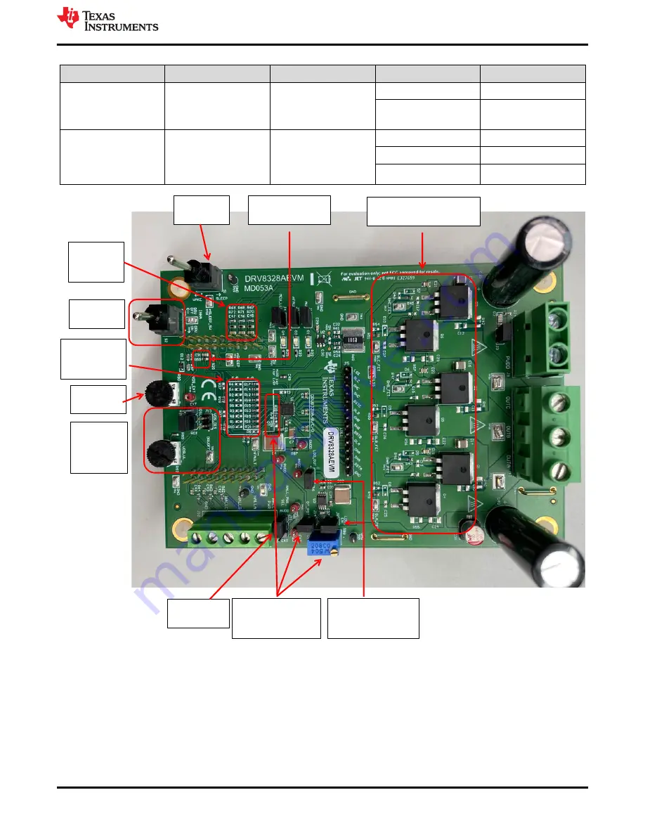
(C) Power stage MOSFETs
and passive components
(G) VDSLVL
pot, select,
and disable
jumpers
(F) Hall
Power select
(E) Dead
me
poten ometer,
jumper, & resistor
(I) DRVOFF
switch
(A) nSLEEP
switch
(B) External CSA
output
lter
(H) DRV8328
A/B or C/D
select
(D) LDO enable and
LDO output enable
jumpers
(J) Phase
voltage
feedback
(K) Speed
pot
Figure 3-6. User-adjustable jumpers, resistors, and switches on DRV8328AEVM
3.4.1 DRV8328A/B Compatibility
The DRV8328AEVM default is the DRV8328A (Hardware variant), but can also be compatible with the
DRV8328B. The main difference is that DRV8328A operates in 6x PWM mode and DRV8328B operates in 3x
PWM mode.
shows the default resistors to select the A/B variant when the DRV8328A or DRV8328B
is used. Ensure resistors R1-R10 are removed, C1 is removed, and resistors R11-R21 are populated (except
R16).
Hardware and Software Overview
SLVUCD3A – NOVEMBER 2021 – REVISED AUGUST 2022
DRV8328xEVM User's Guide
9
Copyright © 2022 Texas Instruments Incorporated


