


Time (s)
V
oltage (2V/div)
0
20m
40m
60m
80m
100m
Acceleration
[OUT+] − [OUT−] (Filtered)
Time (s)
V
oltage (2V/div)
0
20m
40m
60m
80m
100m
Acceleration
[OUT+] − [OUT−] (Filtered)
DRV2624 Demonstration Program
7
SLOU435B – December 2015 – Revised February 2019
Copyright © 2015–2019, Texas Instruments Incorporated
DRV2624 ERM, LRA haptic driver evaluation kit
Figure 7. LRA Closed-Loop Click Waveform
Figure 8. LRA Open-Loop Click Waveform
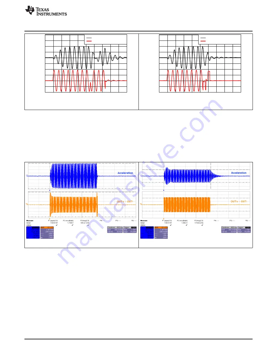
2.2.3
Auto-Resonance Tracking
and
below showcase the advantages of the Smart Loop Architecture which includes
auto-resonance tracking, automatic overdrive, and automatic braking. The two images below show the
difference in acceleration between LRA auto-resonance ON and LRA auto-resonance OFF. Notice that the
acceleration is higher when driven at the resonant frequency. The auto-resonance ON waveform has 1.32
G of acceleration and the auto-resonance OFF waveform has 0.92 G of acceleration. The auto-resonance
ON waveform has 43% more acceleration.
Figure 9. LRA Auto-Resonance ON Waveform (Button 1)
Figure 10. LRA Auto-Resonance OFF Waveform (Button 2)
The reason for higher acceleration can be seen in the acceleration versus frequency graph below. The
LRA has a very narrow operating frequency range due to the properties of a spring-mass system.
Furthermore, the resonance frequency drifts over various conditions such as temperature and drive
voltage. With the Smart Loop auto-resonance feature, the DRV2624 dynamically tracks the exact resonant
frequency to maximize the vibration force.