Texas Instruments DAC8775EVM User Manual Download Page 12

EVM Software Overview

www.ti.com

12

SBAU248 – November 2016

Submit Documentation Feedback

Copyright © 2016, Texas Instruments Incorporated

DAC8775EVM User’s Guide

4

EVM Software Overview

This section describes the use of the EVM software.
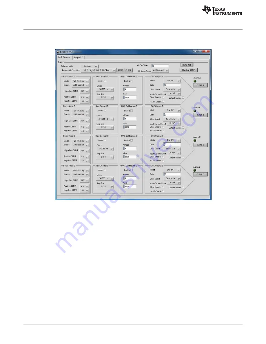
Figure 11

shows the front panel of the EVM GUI.

Figure 11. EVM GUI – Front Panel

4.1

Starting the EVM Software

The EVM software can be operated through the Windows start menu. From the start menu, select All
Programs, and then select DAC8775EVM.

An error will appear if the PC cannot communicate with the EVM. If this error happens, first ensure that
the USB cable is properly connected on both ends. This error can also occur if the USB cable is
connected before the SM-USB-DIG platform power source. Another possible source for this error is a
problem with the USB human interface driver on the PC. Make sure the device is recognized when the
USB cable is plugged in, as indicated by a Windows-generated confirmation sound.

4.2

Reading From and Writing to Registers

The EVM software automatically reads from the DAC8775 when a reset or clear command is issued. To
read from the device in other situations, press the READ ALL button on the EVM GUI. Write actions are
carried out automatically when the value of any element on the GUI is changed.

Summary of Contents for DAC8775EVM

Page 1: ...EVM Software Setup 10 4 EVM Software Overview 12 5 EVM Documentation 15 List of Figures 1 DAC8775EVM Hardware Setup 3 2 DAC8775EVM Block Diagram 3 3 PVDD AVDD AVSS and DVDD Supply Connections 6 4 Digi...

Page 2: ...he contents of the EVM kit Contact the nearest Texas Instruments Product Information Center or visit the Texas Instruments E2E Community http E2E ti com if any component is missing Table 1 Contents of...

Page 3: ...tes with the SM USB DIG platform which provides the power and digital signals used to communicate with the EVM board Connectors on the EVM board allow the user to connect the required external power s...

Page 4: ...s PVDD AVDD to supply VPOSD JP8 1 2 1 2 Selects DC DC Channel D to supply VNEGD 2 3 Selects AVSS to supply VNEGD JP9 Not installed Installed Connects the SM USB DIG supply to DVDD Not installed Discon...

Page 5: ...SEPC is shorted to VOUTA off board JP31 Installed Installed VSENSEPD is shorted to VOUTB onboard Not installed VSENSEPD is shorted to VOUTB off board JP32 Not installed Installed Loads VOUTC IOUTC wit...

Page 6: ...negative supply for the output signal chain may be powered by the DAC8775 internal buck boost converters or by off board supply voltages WARNING Permanent device damage may occur if externally supplyi...

Page 7: ...onfiguration take care to ensure that digital logic thresholds of the host and DAC8775 match and that the absolute maximum ratings of the DAC8775 are not violated 2 5 EVM Features This section describ...

Page 8: ...NSEP_X and VSENSEN_X sense connections may be provided onboard or externally closer to the point of load through terminal blocks J5 J6 J7 or J8 To provide the VSENSEP_X connections onboard install JP1...

Page 9: ...HART FSK communication signals onto the current outputs When injecting the HART signal remove JP28 JP29 JP42 or JP43 and apply the HART signal to pin 1 When a HART signal is not being injected install...

Page 10: ...VDUT Switchable DUT power supply 3 3 V 5 V Hi Z disconnected Note When VDUT is Hi Z all digital I Os are Hi Z as well 7 SPI_CLK SPI clock signal SCLK 8 GND Power return GND 9 SPI_CS1 SPI chip select s...

Page 11: ...e installation process initializes the user is given a choice of selecting the installation directory usually defaulting to C Program Files x86 DAC8775EVM and C Program Files x86 National Instruments...

Page 12: ...EVM If this error happens first ensure that the USB cable is properly connected on both ends This error can also occur if the USB cable is connected before the SM USB DIG platform power source Another...

Page 13: ...of the device to synchronize the GUI and hardware A hardware clear command can be issued through JP12 If a hardware clear is issued the READ ALL button should be pressed to synchronize the GUI and ha...

Page 14: ...asheet 4 6 Slew Rate Controls The slew rate of each channel may be controlled by the slew control registers for each channel By default the slew rate control features are disabled To enable the slew r...

Page 15: ...11 LP_B 12 PVDD_B 13 LN_A 14 PVSS_A 15 LP_A 16 PVDD_A 17 AGND_A 18 VNEG_IN_A 19 VNEG_IN_B 20 SCLK 21 SDIN 22 LDAC 23 SDO 24 SYNC 25 CLR 26 HARTIN_B 27 CCOMP_B 28 HARTIN_A 29 CCOMP_A 30 VSENSEP_B 31 V...

Page 16: ...ND GND GND GND GND GND GND GND GND GND GND GND GND Copyright 2016 Texas Instruments Incorporated PVDD AVDD 100 H L1 AGND_A PVSS_A PVDD_A VPOS_IN_A LN_A LP_A VNEG_IN_A VNEG_IN_A 2k ohm FB1 2k ohm FB2 0...

Page 17: ...ber 2016 Submit Documentation Feedback Copyright 2016 Texas Instruments Incorporated DAC8775EVM User s Guide 5 2 EVM PCB Components Layout Figure 15 shows the layout of the components for the EVM boar...

Page 18: ...A SOD 123 MBRX160 TP Micro Commercial Components 12 D5 D6 D7 D8 D13 D14 D15 D16 D19 D20 D23 D24 Diode TVS Bi 36V 400W SOD323 2 Leads Body 1 9x1 45mm No Polarity Mark CDSOD323 T36SC Bourns 4 D17 D18 D2...

Page 19: ...1 00 k 0 1 1 W 1206 resistor PHP01206E1001BST5 Vishay Dale 1 R39 RES 1 50 ohm 1 0 1W 0603 CRCW06031R50FKEA Vishay Dale 16 TP1 TP2 TP3 TP4 TP5 TP6 TP7 TP8 TP17 TP18 TP19 TP20 TP31 TP32 TP33 TP34 Test...

Page 20: ...sponsible for compliance with all legal regulatory and safety related requirements concerning its products and any use of TI components in its applications notwithstanding any applications related inf...

Reviews: