


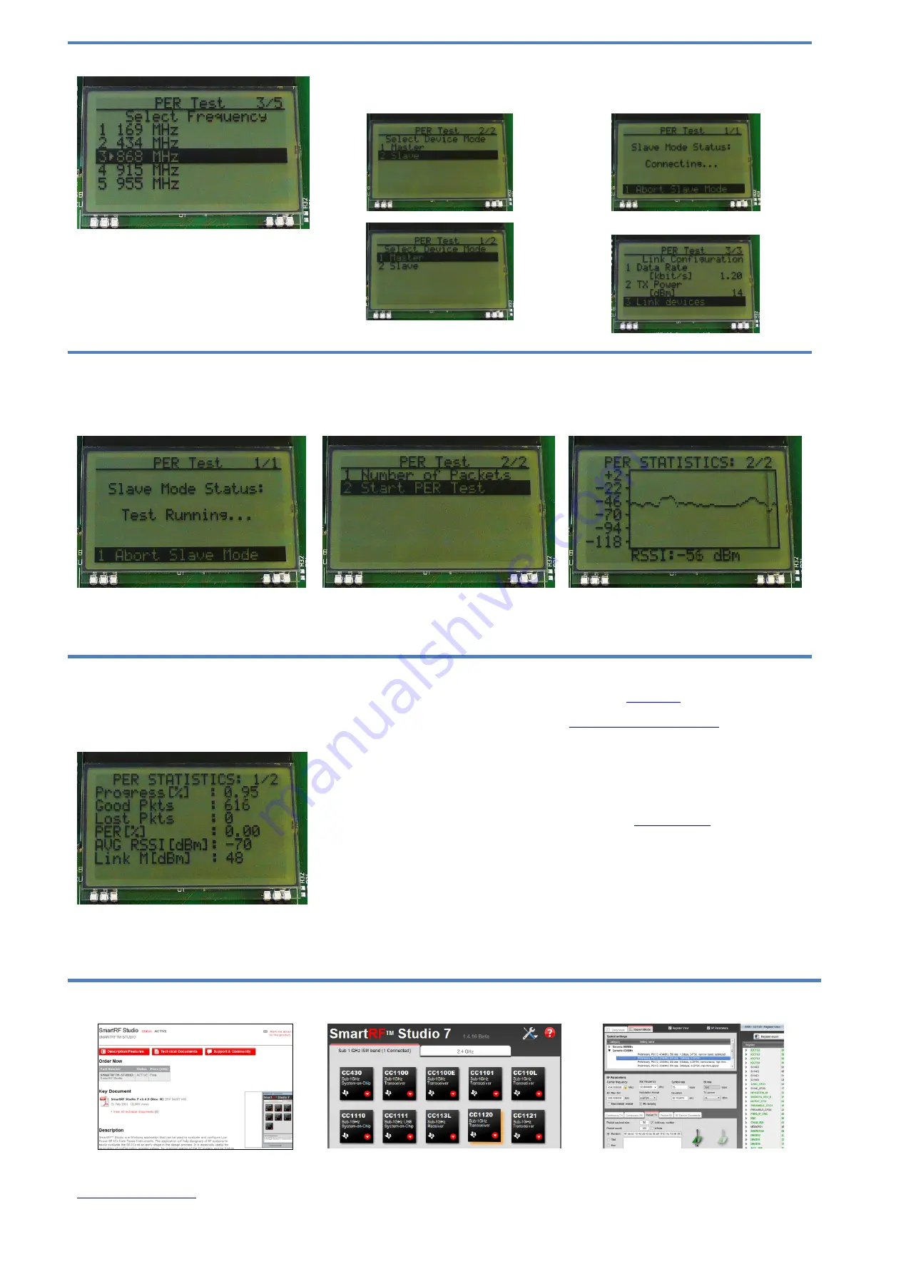
10. Select Frequency
Select which frequency to use for the test. Make
sure that the evaluation modules you have
match the selected frequency.
11. Select Mode
One of the boards must operate as the slave
(transmitter) and the other as master (receiver).
Select Slave
on one board…
…and Master on the other board.
12. Establish Link
The slave node will now wait for a configuration
package from the Master. The configuration
contains the parameters used for the PER test.
The configuration package will be sent when you
select “link devices” on the master node.
13. Link Established
When the initial linking has completed, the slave
node will start the test by continuously
transmitting packets to the master.
14. Start the Receiver (master)
On the master node, you can select the number
of packets you want to receive in order to
calculate the packet error.
When selecting “Start PER Test”, the master
(receiver) will begin to count the number of
received packets and provide some statistics.
15. PER Test Results
The master will display a window that plots the
received signal strength (RSSI) for each packet.
Press the “Up” button to go to the detailed
statistical window.
16. PER Test Results
The statistics window will show the error rate
based on the number of lost or erroneous
packets divided by the total number of packets
that should have been received.
17. Troubleshooting
It you are experiencing problems with this test,
please check the following:
Nothing is shown in the display! Make sure
the mode switches are in the correct
positions (see step 4 above).
Please visit the kit web page and check for
updated SW and documentation. Updated
SW can be downloaded to the device using
IAR EW430 or SmartRF Flash Programmer.
If you get poor PER results at short
distances, try to move the transmitter and
receiver further apart. The CC1125 receiver
may be saturated if it is too close to the other
CC1125 transmitting at full output power.
18. References
Please visit
http://www.ti.com/tool/cc1125dk
On the kit product page, you will find additional
documentation, links
to updated
software
examples and software tools like SmartRF
Studio.
You will also find a lot of information on the TI
E2E forum at
We hope that you will enjoy working with the
CC1125 device.
SmartRF
™ Studio
1. Download and Install
Before connecting SmartRF TrxEB to your PC,
download and install SmartRF Studio from
2. Launch SmartRF Studio
After installing the tool, connect the EB to the PC
using the USB cable and start SmartRF Studio.
Select the “Sub 1 GHz” tab and double click the
highlighted CC1125 device icon.
3. Test the Radio
You can now configure the radio, run
performance tests, export register settings and
run link tests with another CC1125 on a
SmartRF TrxEB connected to the PC.


