


Hardware and Schematic
25
SBOU106A – May 2011 – Revised May 2016
Copyright © 2011–2016, Texas Instruments Incorporated
BUF16821EVM-USB Evaluation Board and Software Tutorial
5.2.10
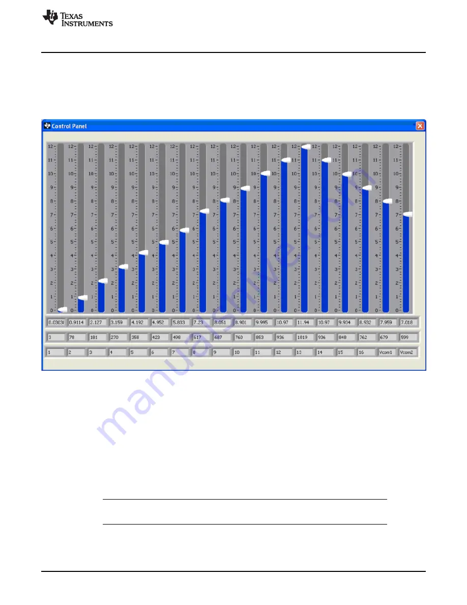
Control Panel Button
Pressing the
Control Panel
button brings up a display panel that allows you to adjust each channel using
a set of graphical sliders, as shown in
. Simply drag the slider to adjust the desired channel
output. The DAC code and corresponding output value of each channel change automatically. This
function is similar to the slider present on the primary BUF16821EVM-USB software window that changes
based on the channel that highlighted (as discussed in the
).
Figure 23. Control Panel Button and Window
5.2.11
Program OTP All Channels Button
Pressing the
Program OTP All Channels
button allows you to program the current gamma curve into the
nonvolatile memory in the BUF16821. All channels (including the V
COM
) are then programmed
simultaneously. The values are stored in the memory bank that is selected via the BKSEL switch (see
Section 3.7.2xx).
6
Hardware and Schematic
This section contains the complete bill of materials, schematic diagram, and PCB layouts for the
BUF16821EVM-USB.
NOTE:
Board layouts are not to scale. These are intended to show how the board is laid out; they
are not intended to be used for manufacturing BUF16821EVM-USB PCBs.