Software
7.12 Stopping and Starting Polling and Balancing
Once the hardware is set up and the GUI settings have been defined, the user can begin polling cell
voltage data, temperature and auxiliary input data, and enable and disable balancing.
Near the lower right-hand corner of the GUI in the
Poll
group box, find the
Poll Start
button highlighted in
green. When clicked, the GUI begins polling cell voltage and auxiliary input data. Set the polling rate by
using the
Report Rate
drop-down menu found below the graph. Define a polling rate of 200 ms to 5
seconds, though it is recommended to use a rate no faster than 500 ms, which is the default rate selected.
The data can be saved to a user-defined .tsv file using controls on the
Logging
tab. The cell voltage data
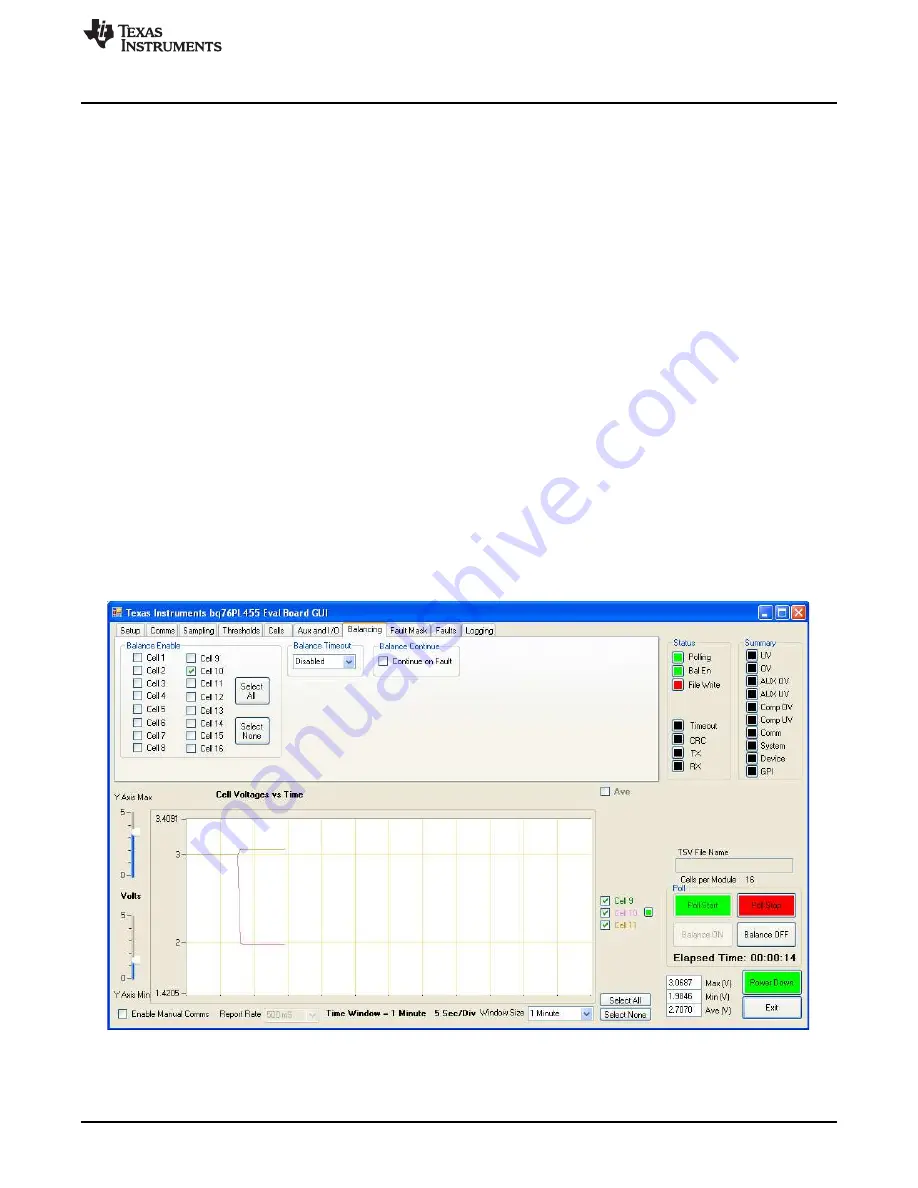
is displayed in real time across the
Cell Voltages vs Time
graph, as seen in
. Change the time
scale using the Window Size drop-down menu, and define the time scale from 1 minute to 12 hours. The
voltage scale is changed using the sliders to the left of the graph.
The
Balance ON
and
Balance OFF
buttons start and stop balancing, respectively. The
Balance ON
and
Balance OFF
buttons are not enabled unless at least one cell has been selected on the
Balancing
tab.
Also, the
Balance ON
button is not enabled if the bq76PL455A-Q1 is already balancing, and the
Balance
OFF
button is not enabled if the bq76PL455A-Q1 is not already balancing.
If there were no faults during the activation of the balancing function, the green balancing status LED (
Bal
En
) near the upper right hand corner of the GUI screen and cell balancing indicators next to selected
cell(s) turns green. If, on the other hand, a fault occurred during balance enabling, the balancing status
LED (
Bal En
) turns red, and all balancing is disabled. For safety, clear all faults before balancing is re-
started.
As shown in the Cell 10 example in
, when balancing is enabled, the voltage of the balanced cell
in the
Cell Voltage vs Time
view drops. It can also be seen that during balancing, the measurement of the
adjacent Cells 9 and 11 is also affected as these share common sense lines in the battery cable. It is
important to understand that measurement accuracy is affected by the balancing process and is due to the
presence of the balancing current flowing in the measurement sense lines which have non-zero
resistance.
Figure 26. Cell 10 Balancing Example
39
SLUUBA7A – April 2015 – Revised July 2015
bq76PL455EVM and GUI User Guide
Copyright © 2015, Texas Instruments Incorporated


