Charge Current (A)
Charg
e Efficie
nc
y (%
)
0.3
0.6
0.9
1.2
1.5
1.8
2.1
2.4
2.7
3
75
80
85
90
95
100
Char
VBUS = 5V
VBUS = 9V
VBUS = 12V
VBUS = 15V
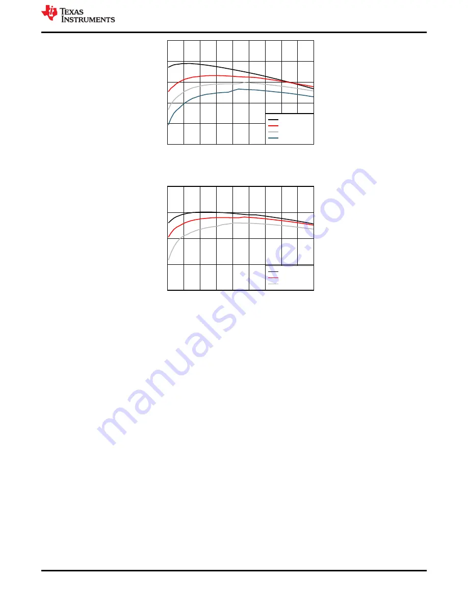
Figure 2-2. BQ25306EVM 1-Cell Efficiency
Charge Current (A)
Charg
e Efficie
nc
y (%
)
0.3
0.6
0.9
1.2
1.5
1.8
2.1
2.4
2.7
3
80
85
90
95
100
Char
VBUS = 10V
VBUS = 12V
VBUS = 15V
Figure 2-3. BQ25306EVM 2-Cell Efficiency
2.3.6 Helpful Tips
1. BQ25306EVM is configured by default to operate with TS in normal range. If external thermistor is available,
connect external thermistor at J1(2)-EXT_TS and J1(1)-PGND, and remove R14.
2. The leads and cables to the various power supplies, batteries and loads have resistance. The current meters
also have series resistance. The charger dynamically reduces charge current depending on the voltage
sensed at its VBUS pin (using the VINDPM feature), BAT pin (as part of normal termination), and TS pin
(through its battery temperature monitoring feature via battery thermistor). Therefore, voltmeters must be
used to measure the voltage as close to the IC pins as possible instead of relying on the digital readouts of
the power supply.
3. When using a source meter that can source and sink current as your battery simulator, TI highly recommends
adding a large (1000+ μF) capacitor at the EVM BATTERY and GND connectors in order to prevent
oscillations at the BAT pin due to mismatched impedances of the charger output and source meter input
within their respective regulation loop bandwidths. Configuring the source meter for 4-wire sensing eliminates
the need for a separate voltmeter to measure the voltage at the BAT pin.
When using 4-wire sensing, always ensure that the sensing leads are connected in order to prevent
accidental overvoltage by the power leads.
3 PCB Layout Guideline
Minimize the switching node rise and fall times for minimum switching loss. Proper layout of the components
minimizing high-frequency current path loop is important to prevent electrical and magnetic field radiation and
high-frequency resonant problems. This PCB layout priority list must be followed in the order presented for
proper layout:
Test Setup and Results
SLUUC50A – MARCH 2020 – REVISED DECEMBER 2020
BQ25306 (BMS005) Evaluation Module
5
Copyright © 2020 Texas Instruments Incorporated


