www.ti.com
Board Layout
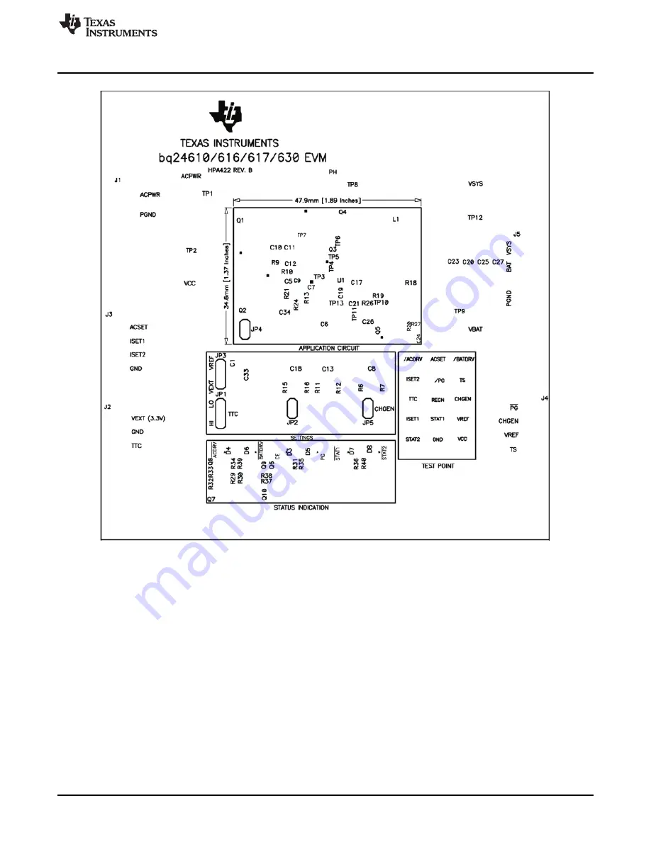
Figure 8. Top Silkscreen
17
SLUU396A – January 2010 – Revised July 2010
bq2461x/bq2463x EVM (HPA422) Multi-Cell Synchronous Switch-Mode Charger
Copyright © 2010, Texas Instruments Incorporated
Page 1: ...s Board Layout and Schematics 8 4 1 Bill of Materials 8 5 Board Layout 11 6 Schematics 19 List of Figures 1 Original Test Setup for HPA422 bq2461x bq2463x EVM 5 2 Top Layer 11 3 2nd Layer 12 4 3rd Lay...
Page 2: ...n The bq2461x bq2463x automatically restarts the charge cycle if the battery voltage falls below an internal threshold and enters a low quiescent current sleep mode when the input voltage falls below...
Page 3: ...n LED has no power source when off VPULLUP setting Jumper On 1 2 VPULLUP and JP3 1 2 Connect VPULLUP to VREF VREF 2 3 Connect VPULLUP to VEXT JP4 The pull up voltage source of ACDRV and BATDRV LED log...
Page 4: ...Jxx terminals are shorted Jxx OFF Internal jumper Jxx terminals are open Jxx YY ON Internal jumper Jxx adjacent terminals marked as YY are shorted Measure A B Check specified parameters A B If measure...
Page 5: ...series with a current meter multimeter to J1 VIN GND 3 Connect a voltage meter across J1 VIN GND 4 Set the power supply 2 for 0V 100mVDC 1 0 0 1A current limit and then turn off supply 5 Connect the...
Page 6: ...urn on the Load 2 Set the output voltage to 12V bq2461x or 2V bq2463x 3 Connect the output of the Load 1 in series with a current meter multimeter to J5 SYS GND Make sure a voltage meter is connected...
Page 7: ...RV off D6 BATDRV on D5 PG off D7 STAT1 off D8 STAT2 off 8 Turn off power supply 2 and 3 Set JP3 on 1 2 VPULLUP and VREF 3 PCB Layout Guideline 1 It is critical that the exposed power pad on the backsi...
Page 8: ...805 STD STD 2 2 2 2 1 0uF 50V C12 C14 Capacitor Ceramic 50V X5R 20 1206 STD STD 1 1 1 1 2 2uF 50V C2 Capacitor Ceramic 50V X7R 20 1206 STD STD 0 0 0 0 C32 Capacitor Ceramic 50V X7R 20 1206 STD STD 6 6...
Page 9: ...Std 2 2 2 2 10k R29 R30 Resistor Chip 1 16W 1 603 Std Std 6 6 6 6 100k R3 Resistor Chip 1 16W 1 603 Std Std R20 R32 R33 R37 R38 1 1 1 1 10k R16 Resistor Chip 1 10W 1 805 Std Std 1 1 1 1 100k R15 Resi...
Page 10: ...2N7002DICT Q6 Q8 Q9 MOSFET N ch 60V 115mA SOT23 2N7002DICT Vishay Liteon 1 2Ohms 3 3 3 3 SI4401BDY Q1 Q2 Q5 MOSFET PChan 40V 18A S0 8 SI4401BDY Vishay T1 GE Note 5 9 2millohm FDS4141 Siliconxi FDS414...
Page 11: ...om Board Layout 5 Board Layout Figure 2 Top Layer 11 SLUU396A January 2010 Revised July 2010 bq2461x bq2463x EVM HPA422 Multi Cell Synchronous Switch Mode Charger Copyright 2010 Texas Instruments Inco...
Page 12: ...oard Layout www ti com Figure 3 2nd Layer 12 bq2461x bq2463x EVM HPA422 Multi Cell Synchronous Switch Mode Charger SLUU396A January 2010 Revised July 2010 Copyright 2010 Texas Instruments Incorporated...
Page 13: ...ww ti com Board Layout Figure 4 3rd Layer 13 SLUU396A January 2010 Revised July 2010 bq2461x bq2463x EVM HPA422 Multi Cell Synchronous Switch Mode Charger Copyright 2010 Texas Instruments Incorporated...
Page 14: ...ard Layout www ti com Figure 5 Bottom Layer 14 bq2461x bq2463x EVM HPA422 Multi Cell Synchronous Switch Mode Charger SLUU396A January 2010 Revised July 2010 Copyright 2010 Texas Instruments Incorporat...
Page 15: ...w ti com Board Layout Figure 6 Top Assembly 15 SLUU396A January 2010 Revised July 2010 bq2461x bq2463x EVM HPA422 Multi Cell Synchronous Switch Mode Charger Copyright 2010 Texas Instruments Incorporat...
Page 16: ...d Layout www ti com Figure 7 Bottom Assembly 16 bq2461x bq2463x EVM HPA422 Multi Cell Synchronous Switch Mode Charger SLUU396A January 2010 Revised July 2010 Copyright 2010 Texas Instruments Incorpora...
Page 17: ...ti com Board Layout Figure 8 Top Silkscreen 17 SLUU396A January 2010 Revised July 2010 bq2461x bq2463x EVM HPA422 Multi Cell Synchronous Switch Mode Charger Copyright 2010 Texas Instruments Incorpora...
Page 18: ...Layout www ti com Figure 9 Bottom Silkscreen 18 bq2461x bq2463x EVM HPA422 Multi Cell Synchronous Switch Mode Charger SLUU396A January 2010 Revised July 2010 Copyright 2010 Texas Instruments Incorpor...
Page 19: ...tics 6 Schematics Figure 10 bq2461x bq2463x EVM Schematic 19 SLUU396A January 2010 Revised July 2010 bq2461x bq2463x EVM HPA422 Multi Cell Synchronous Switch Mode Charger Copyright 2010 Texas Instrume...
Page 20: ...oduct This notice contains important safety information about temperatures and voltages For additional information on TI s environmental and or safety programs please contact the TI application engine...
Page 21: ...h statements TI products are not authorized for use in safety critical applications such as life support where a failure of the TI product would reasonably be expected to cause severe personal injury...