Texas Instruments BOOST-DAC8730-HART User Manual Download Page 9

www.ti.com

BOOST-DAC8730-HART Software Overview

9

SLAU699 – May 2017

Submit Documentation Feedback

Copyright © 2017, Texas Instruments Incorporated

BOOST-DAC8730-HART Evaluation Module

5

BOOST-DAC8730-HART Software Overview

This section discusses how to use the BOOST-DAC8730-HART software.

5.1

Starting the BOOST-DAC8730-HART Software

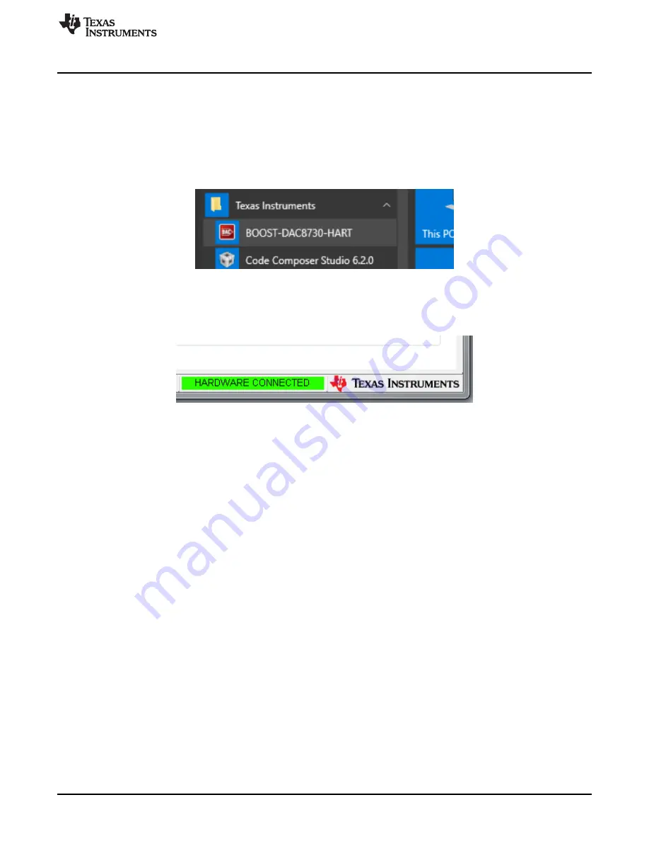
Once the hardware connections are established and jumper settings configured, power on the BOOST-
DAC8730-HART with the loop-supply voltage. Next, launch the software located in the

Texas Instruments

folder of the

Start All Programs

menu, and select the BOOST-DAC8730-HART icon.

Figure 8. BOOST-DAC8730-HART GUI Location

If the LaunchPad is properly connected to the BOOST-DAC8730-HART, the GUI should automatically
display "HARDWARE CONNECTED" on the lower left of the GUI, as seen in

Figure 9

.

Figure 9. BOOST-DAC8730-HART GUI – Power On

If the LaunchPad has a faulty connection, or is not connected at all, the GUI will launch in DEMO mode. If
this text appears while the LaunchPad device is connected, then power off the loop-supply voltage, unplug
the LaunchPad, and close the GUI. Reconnect the LaunchPad and ensure that the connectors are
correctly aligned. After this, verify the USB extender cable is properly connected to both the LaunchPad
and PC. Reapply the loop-supply voltage and re-launch the GUI. This issue can also occur if the MSP430
driver is installed incorrectly, and so the BOOST-DAC8730-HART software may need to be reinstalled.

5.2

BOOST-DAC8730-HART Software Features

The following subsections describe the functionality of each page of the BOOST-DAC8730-HART GUI.

5.2.1

BOOST-DAC8730-HART Low Level Configuration Page

The BOOST-DAC8730-HART features a

Register Map

page that allows access to low-level

communication by directly writing to and reading from the registers of the BOOST-DAC8730-HART.
Selecting a register on the

Register Map

list will present a description of the values in that register, and

also display register information such as the address, default value, size, and current value. The register
values can be modified by either writing directly to the value column or selecting the bit individually. This is
shown in

Figure 10

.

Summary of Contents for BOOST-DAC8730-HART

Page 1: ...lation 5 3 3 Installing Drivers and MSP430FR5969 LaunchPad Firmware 6 4 BOOST DAC8730 HART Hardware Overview 7 4 1 Electrostatic Discharge Warning 7 4 2 Connecting the BOOST DAC8730 HART 7 4 3 BOOST D...

Page 2: ...ntrol operation amplifier HART or FF PA modem internal reference and power tree 1 1 BOOST DAC8730 HART Kit Contents Table 1 details the contents of the kit Contact the TI Product Information Center or...

Page 3: ...necessary LaunchPad drivers and MSP430FR5969 firmware Additionally the Graphical User Interface GUI provides an interactive interface that syncs communication between the MSP430FR5969 LaunchPad and DA...

Page 4: ...lowing MSP430FR5969 LaunchPad J13 jumpers must be set to the configuration shown in Table 3 WARNING If the jumper connections are not configured as in Table 3 the BOOST DAC8730 HART and MSP430FR5969 w...

Page 5: ...ings The software should also be compatible with other Windows operating systems 3 2 BOOST DAC8730 HART Software Installation The software is available through the product folder on the TI website Onc...

Page 6: ...730 tab under the Pages field and press the Install MSP430 Drivers button as shown in Figure 6 Figure 6 Install MSP430 Drivers Button Once pressed a batch file will execute from the software and insta...

Page 7: ...Default setting GND 4 1 Electrostatic Discharge Warning Many of the components on the BOOST DAC8730 HART are susceptible to damage by electrostatic discharge ESD Customers are advised to observe prop...

Page 8: ...across the sense resistor Table 5 BOOST DAC8730 HART Power Supply Configuration Connector Connection Type Description J2 Terminal block External loop supply connection A loop supply voltage of 24 V is...

Page 9: ...he LaunchPad device is connected then power off the loop supply voltage unplug the LaunchPad and close the GUI Reconnect the LaunchPad and ensure that the connectors are correctly aligned After this v...

Page 10: ...er options selectable by the user are the Update Mode Write Selected red box Read Selected orange box Write Modified gray box and Read All yellow box icons All icons are displayed in Figure 11 Figure...

Page 11: ...or Set PWM the appropriate code range is 0x1000 0xEFFF The HART interface is controlled via UART which is controlled in the firmware of the MSP430FR5969 device To create a transmit packet type the dat...

Page 12: ...Nibble Reply 2nd Byte Description RESET 0000 PWM A 25 ms timeout has occurred and an updated DAC data is required After 10 consecutive RESET commands a resynchronization occurs IDLE 0010 PWM TX HART o...

Page 13: ...27 CAP3 10 NC 13 BF_INP1 46 BF_OUT2 49 CAP5 52 SLEW1 55 GND 4 CAP1 7 VEE 16 VSHUNT_CFG 19 DCDC_FB 22 GND 25 CS 32 VCCIO 35 XTAL2 38 VCCIO_CFG1 41 CAP2 9 GND 12 REG_IN 45 BF_INN2 48 VPP 51 MOD_IN 54 I...

Page 14: ...mentation Feedback Copyright 2017 Texas Instruments Incorporated BOOST DAC8730 HART Evaluation Module 6 2 BOOST DAC8730 HART PCB Components Layout Figure 14 shows the layout of the components for the...

Page 15: ...a CAP CERM 10 F 25 V 10 X7R 0805 0805 12 C16 1 390pF GRM1555C1H391JA01D Murata CAP CERM 390 pF 50 V 5 C0G NP0 0402 0402 13 C17 1 100pF GRM1555C1H101JA01D Murata CAP CERM 100 pF 50 V 5 C0G NP0 0402 040...

Page 16: ...1 100k CRCW0603100KFKEA Vishay Dale RES 100 k 1 0 1 W 0603 0603 42 R14 1 402k CRCW0603402KFKEA Vishay Dale RES 402 k 1 0 1 W 0603 0603 43 R15 1 8 25k CRCW06038K25FKEA Vishay Dale RES 8 25 k 1 0 1 W 06...

Page 17: ...set forth above or credit User s account for such EVM TI s liability under this warranty shall be limited to EVMs that are returned during the warranty period to the address designated by TI and that...

Page 18: ...the antenna types listed in the user guide with the maximum permissible gain and required antenna impedance for each antenna type indicated Antenna types not included in this list having a gain great...

Page 19: ...t the EVM user guide prior to connecting any load to the EVM output If there is uncertainty as to the load specification please contact a TI field representative During normal operation even with the...

Page 20: ...OST OF REMOVAL OR REINSTALLATION ANCILLARY COSTS TO THE PROCUREMENT OF SUBSTITUTE GOODS OR SERVICES RETESTING OUTSIDE COMPUTER TIME LABOR COSTS LOSS OF GOODWILL LOSS OF PROFITS LOSS OF SAVINGS LOSS OF...

Page 21: ...TI Resource NO OTHER LICENSE EXPRESS OR IMPLIED BY ESTOPPEL OR OTHERWISE TO ANY OTHER TI INTELLECTUAL PROPERTY RIGHT AND NO LICENSE TO ANY TECHNOLOGY OR INTELLECTUAL PROPERTY RIGHT OF TI OR ANY THIRD...

Reviews: