BOOST-DAC8730-HART Software Overview
9
SLAU699 – May 2017
Copyright © 2017, Texas Instruments Incorporated
BOOST-DAC8730-HART Evaluation Module
5
BOOST-DAC8730-HART Software Overview
This section discusses how to use the BOOST-DAC8730-HART software.
5.1
Starting the BOOST-DAC8730-HART Software
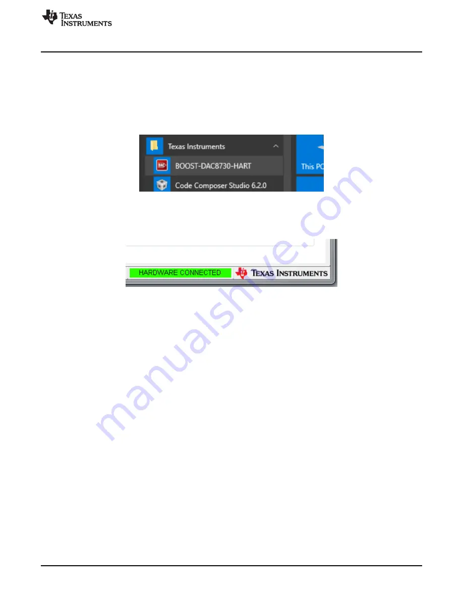
Once the hardware connections are established and jumper settings configured, power on the BOOST-
DAC8730-HART with the loop-supply voltage. Next, launch the software located in the
Texas Instruments
folder of the
Start All Programs
menu, and select the BOOST-DAC8730-HART icon.
Figure 8. BOOST-DAC8730-HART GUI Location
If the LaunchPad is properly connected to the BOOST-DAC8730-HART, the GUI should automatically
display "HARDWARE CONNECTED" on the lower left of the GUI, as seen in
.
Figure 9. BOOST-DAC8730-HART GUI – Power On
If the LaunchPad has a faulty connection, or is not connected at all, the GUI will launch in DEMO mode. If
this text appears while the LaunchPad device is connected, then power off the loop-supply voltage, unplug
the LaunchPad, and close the GUI. Reconnect the LaunchPad and ensure that the connectors are
correctly aligned. After this, verify the USB extender cable is properly connected to both the LaunchPad
and PC. Reapply the loop-supply voltage and re-launch the GUI. This issue can also occur if the MSP430
driver is installed incorrectly, and so the BOOST-DAC8730-HART software may need to be reinstalled.
5.2
BOOST-DAC8730-HART Software Features
The following subsections describe the functionality of each page of the BOOST-DAC8730-HART GUI.
5.2.1
BOOST-DAC8730-HART Low Level Configuration Page
The BOOST-DAC8730-HART features a
Register Map
page that allows access to low-level
communication by directly writing to and reading from the registers of the BOOST-DAC8730-HART.
Selecting a register on the
Register Map
list will present a description of the values in that register, and
also display register information such as the address, default value, size, and current value. The register
values can be modified by either writing directly to the value column or selecting the bit individually. This is
shown in


