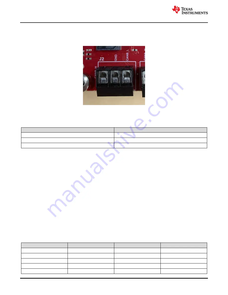
2.4.4 CAN-B Interface Connector (J2)
The J2 connector provides the CANB_L and CANB_H signals from the onboard can CAN-FD transceiver
(TCAN1043ADYYRQ1). These can be directly wired to the CAN bus.
Figure 2-8. CAN_B Connector
provides the pin assignment details for the CAN_B connector connector.
Table 2-4. J2 Pin Assignment
Pin Number
Description
1
CAN_L
2
GND
3
CAN_H
2.4.5 Ethernet Ports (J4 and J9)
The AWR2944EVM supports two RGMII Ethernet ports to provide the connection to the network. The J4
connector provides access over a MATEnet port (9-2304372-9 connector) via a DP83TC812R-Q1 PHY. The
J9 port provides access over an RJ45 port via a DP83867ERGZR PHY. By default, the RGMII interfaces is
connected to the J9 port only. In order to access the RGMII interface over the J4 connector several resistors
must be populated. For more details please see
and refer to the Schematic, BOM, and Assembly
and Database and Layout files.
This interface is intended to operate primarily as a 100Mbps ECU interface. It can also be used as an
Instrumentation Interface.
It supports following features:
• Full Duplex 10Mbps/100Mbps wire rate Interface to Ethernet PHY over RGMII, parallel interface
• MDIO Clause 22 and 45 PHY management interface
• IEEE 1588 Synchronous Ethernet support
The Ethernet port is interfaced to the AWR2944 through the Ethernet PHY and is used to stream the captured
data over the network to the host PC.
shows the Ethernet RJ45 Mag-Jack connector, and
provides the connector pin details.
Table 2-5. J9 Pin Assignment
Pin Number
Description
Pin Number
Description
1
GND
2
Test point
3
ETH_D4P
4
ETH_D4N
5
ETH_D3P
6
ETH_D3N
7
ETH_D2P
8
ETH_D2N
9
ETH_D1P
10
ETH_D1N
Hardware
18
AWR2944EVM User’s Guide
Copyright © 2021 Texas Instruments Incorporated


