


6 EVM Operation
6.1 Connecting the Hardware and Starting Software
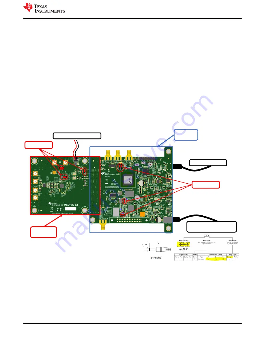
1. After installing the software, connect the EVM and set jumpers as shown in
.
2. Connect a 5-V wall-wart connector or other power source for the TSWDC155EVM (sold separately). The
TSWDC155EVM user guide provides information on this power source.
3. Physically connect J1 of the TSWDC155EVM to J27 of the ADS9218EVM. This component is the digital
communications and power signal connection.
4. Connect the USB on the TSWDC155EVM to the computer.
5. Set jumper J18 to the FMC_PWR position to allow for an external power connection. Connect an external
5.2-V to 5.5-V supply on screw terminal connection J17.
6. Start the software GUI as described in
7. Press the buttons (
Initialize USB
,
Power Up
,
Program FPGA
, and
Initialize ads98xx
) on the
Config
tab to
power up and configure the EVM (see
8. Connect a differential signal generator. The maximum input range is ±3.2 V, and the common-mode input is
2.048 V.
9. Press the
EN SYNC
button on the
Capture
tab. Select the number of samples to be at least 32k, and choose
the Hanning window type for best frequency domain results. Press the
Start Capture
button to collect and
ADS9218EVM
(MED1613E2)
J13: 5V, 3A, 15W power adapter
( or Bench supply)
TSWDC155
(DC155A)
J5, J6, J29, J33
J8: USB- C to USB- A cable
J17: 5.3V- 5.5V, 1A, Bench supply
J5, J11, J18
Figure 6-1. Connecting the Hardware
EVM Operation
SBAU409 – SEPTEMBER 2022
ADS9218EVM-PDK Evaluation Module
13
Copyright © 2022 Texas Instruments Incorporated