


4.2 Data Capture
The
Data Capture
icon selects the available charting options for displaying conversion data. The data options,
Time Domain
,
Histogram
, and
FFT
displays. However, the FFT plot and
information may have little meaning because the ADS1x48 is primarily a dc measurement device.
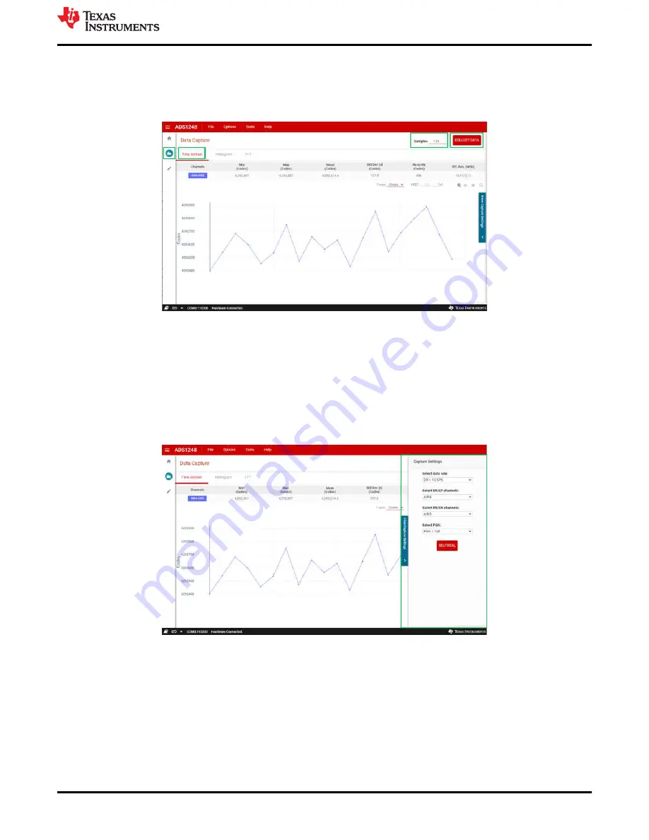
Figure 4-5. Data Capture Window
) is viewable on the right side of the
Chart
window. By clicking the
Show Capture Settings
slide-out, various configurations and displays are selectable. The drop-down menus
available in the
Capture Settings
slide-out are:
•
Select data rate
for the data output conversion rate
•
Select MUXP channels
and
Select MUXN channels
for choosing the desired input channels to be measured
•
Select PGA
for choosing the required input signal amplification
•
SELFOCAL
button for performing a device (ADC) offset calibration
Figure 4-6. Capture Settings Slide-Out
To collect data, select the number of
Samples
to collect in the upper right corner of the capture window. To
capture data, press the
Collect Data
button next to the
Samples
setting (shown in
).
Conversion data collects when the
Collect Data
button is pressed, after which the button changes to read
Stop
Collect
. Pressing the
Stop Collect
button stops the collection of conversion data; otherwise the data are collected
for the chosen number of
Samples
. The number of
Samples
can be changed prior to pressing
Collect Data
by directly entering the desired number of samples or by clicking on the up and down arrows. The number of
samples cannot be changed while data are being collected.
ADS1x48EVM GUI
SBAU378A – SEPTEMBER 2021 – REVISED JANUARY 2022
ADS1x48EVM Evaluation Module
31
Copyright © 2022 Texas Instruments Incorporated