ADS1115EVM-PDK Kit Operation
5.3
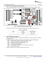
Default Jumper Settings and Switch Positions
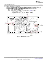
shows the jumpers found on the EVM and the respective factory default conditions for each.
Figure 1. ADS1115EVM Default Jumper Locations
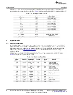
lists the switches found on the EVM and the respective factory default conditions for each.
Table 5. List of Switches
Switch
Position
Switch Description
S1
Right (default)
VDD = +3.3VD
Center
VDD = +5VD
Left
VDD = +VA
6
ADS1115EVM-PDK Kit Operation
This section provides information on using the ADS1115EVM-PDK, including setup, program installation,
and program usage.
To prepare to evaluate the ADS1115 with the ADS1115EVM-PDK, complete the following steps:
Step 1.
Install the ADCPro software (if not already installed) on a PC.
Step 2.
Install the ADS1115EVM-PDK EVM plug-in software.
Step 3.
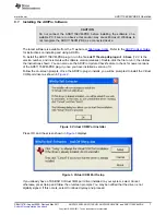
Complete the USB driver installation process.
Step 4.
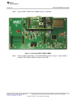
Set up the ADS1115EVM-PDK.
Step 5.
Connect the ADS1115EVM-PDK to the computer with a USB cable.
Step 6.
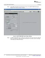
Run the ADCPro software.
Each task is described in the subsequent sections of this document.
6
ADS1015EVM, ADS1115EVM, ADS1015EVM-PDK, and ADS1115EVM-PDK
SBAU157B
–
August 2009
–
Revised May 2011
Copyright
©
2009
–
2011, Texas Instruments Incorporated


